
Fuel Pump Voltage Drop vs Pressure 1999
 02-03-2016, 07:31 PM
#22
SADFab Destructive Testing Engineer


iTrader: (5)
Join Date: Apr 2014
Location: Beaverton, USA
Posts: 18,642
Total Cats: 1,866
Did some more research. It is barely touched on in the MS3 manual, but it does state that we need a solid state relay to do it.
Anyone documented this before?
Anyone documented this before?

Reply
 0
0

0
02-03-2016, 08:14 PM
#23

Most stock cars use PWM driven pumps to maintain rail pressure anymore, the GT500 is one of them.
With a AFPR in line, plus your fuel pressure sensor, all you'd need to do is make a few pulls logging pressure while you lower PWM duty cycle to the pump.
Go as low as you can while still allowing the FPR to maintain proper pressure and that's it.
Solenoid relays don't trigger fast enough, you just need a DC 12V solid state relay capable of the full current draw of the pump.
http://www.ebay.com/itm/Sunkee-Solid...IAAOSwu4BVhVxM
Tiny can add PWM outputs to my MS2, right?
Last edited by deezums; 02-03-2016 at 08:48 PM.
Reply
0
0
02-03-2016, 08:53 PM
#24
Boost Pope

iTrader: (8)
Join Date: Sep 2005
Location: Chicago. (The less-murder part.)
Posts: 33,456
Total Cats: 6,874
And while using a solid-state relay is one (clunky and expensive but easy) way to do it, you can also just use a big, well-heatsunk FET. 20A is a lot of current, but it's not a big deal in the grand scheme of things so long as you're using PWM to control it rather than a linear driver.
Basically, you're just building a high-current version of an EBC driver.

Reply
0
0
02-03-2016, 10:07 PM
#25
Supporting Vendor

iTrader: (33)
Join Date: Jul 2006
Location: atlanta-ish
Posts: 12,659
Total Cats: 134
Using the stock wiring would be silly since we're talking about a high current fuel pump and solid state relay.

Reply
0
0
02-03-2016, 10:09 PM
#26
SADFab Destructive Testing Engineer
iTrader: (5)
Join Date: Apr 2014
Location: Beaverton, USA
Posts: 18,642
Total Cats: 1,866
Obviously not the stock wiring completely. But replacing the stock relay with a solidstate and then setting up PWM.
Joe tell me more about how you would set up the FET.
Joe tell me more about how you would set up the FET.
Reply
0
0
02-03-2016, 10:10 PM
#27
Supporting Vendor
iTrader: (33)
Join Date: Jul 2006
Location: atlanta-ish
Posts: 12,659
Total Cats: 134
Most stock cars use PWM driven pumps to maintain rail pressure anymore, the GT500 is one of them.
With a AFPR in line, plus your fuel pressure sensor, all you'd need to do is make a few pulls logging pressure while you lower PWM duty cycle to the pump.
Go as low as you can while still allowing the FPR to maintain proper pressure and that's it.
Solenoid relays don't trigger fast enough, you just need a DC 12V solid state relay capable of the full current draw of the pump.
Sunkee Solid State Relay SSR 25 DD DC DC 25A 3 32VDC 5 60V DC SSR 25DD New | eBay
Tiny can add PWM outputs to my MS2, right?
You can turn down duty cycle until AFR changes, or just set a table somewhat arbitrarily with 3 break points and tune around it. Most OEs that use PWM fuel pump DO NOT run closed loop fuel pressure control. IIRC only Ford does. Until we get to DI engines, which is a completely different story.
Don't get an ebay solid state relay or FET. Too many counterfeits.
Reply
0
0
02-03-2016, 10:13 PM
#28
Supporting Vendor
iTrader: (33)
Join Date: Jul 2006
Location: atlanta-ish
Posts: 12,659
Total Cats: 134
You can use a large FET in place of a solid state relay. Look up the high side drivers that are used for progressive nitrous control; you could run a fuel pump off one of those. If you don't want to read a data sheet, just get a Hella solid state relay from a known good vendor (like Summit). It's just a giant MOSFET.
Do not source the relay or driver from ebay or amazon. I see clones all the time, and they suck.
Reply
0
0
02-03-2016, 10:31 PM
#29
Boost Pope
iTrader: (8)
Join Date: Sep 2005
Location: Chicago. (The less-murder part.)
Posts: 33,456
Total Cats: 6,874
Treat the fuel pump like you would a low-impedance fuel injector.
Connect the positive side of the pump, through a mechanical relay, directly to b+. The relay is controlled by the FP output of the ECU, and is there simply as a safety cutoff. For academic purposes, assume the + side of the pump is wired directly to alternator or battery +.
On the negative side of the pump, instead of connecting it directly to ground, run it through an N-channel enhancement mode MOSFET (pump - to Drain, ground to Source.) Wire the Gate of said FET to a PWM output of the ECU with a pullup, and map the output pin inversely to injector DC% (inversely because the circuit is inverting), with an effective minimum output DC of, I dunno, maybe 25%. (Trial and error here to find the minimum setpoint which maintains, and a curve which delivers, desired fuel pressure across the operating range.)
And cats. Always cats.
Last edited by Joe Perez; 02-03-2016 at 10:45 PM.
Reply
0
0
02-04-2016, 01:13 AM
#31
Elite Member
Thread Starter
iTrader: (16)
Join Date: Aug 2007
Location: Houston, TX
Posts: 9,348
Total Cats: 521
Dumb question, but I'm running two pumps of different size. Is it ok to wire both pumps to the same solid state relay, so long as the relay is spec'd to handle the power of both pumps? I don't see why not, but thought I'd ask.
Reply
0
0
02-04-2016, 07:32 AM
#33
Boost Pope
iTrader: (8)
Join Date: Sep 2005
Location: Chicago. (The less-murder part.)
Posts: 33,456
Total Cats: 6,874
A note about solid state relays: some are rated only to handle AC loads. Because of their internal construction, they will only switch off at a zero-crossing of the AC waveform of the load. A DC load will never have a zero-crossing event, so it'll never switch off if an AC-only SSR is used to control it.
Irrelevant to this discussion, AC-rated SSRs also cannot be used to PWM control AC loads, for the same reason, unless the circuit driving them operates synchronously with the incoming AC and is smart enough to back-calculate the turn-on point relative to the zero-crossing turn-off point.
Irrelevant to this discussion, AC-rated SSRs also cannot be used to PWM control AC loads, for the same reason, unless the circuit driving them operates synchronously with the incoming AC and is smart enough to back-calculate the turn-on point relative to the zero-crossing turn-off point.
Reply
0
0
02-04-2016, 10:59 AM
#34
Elite Member

Join Date: Jul 2005
Posts: 6,420
Total Cats: 84
How fast do those typical DC SSR's respond? How fast can you PWM them?
If you are using a MOSFET you can PWM them at a few hundred Hz.
Also, you will greatly reduce the heating in the SSR or big MOSFET, and also reduce the duty cycle requirements of the pump, if you put a bigass diode across them for the motor / inductive currents to flow, during the 'off' period of the PWM.
In fact, I would NOT go without said diode. There will probably be way too much heating in the SSR/FET otherwise.
Here's one suitable diode. Will need heatsinking because will dissipate ~10W.
DSS60-0045B IXYS | Discrete Semiconductor Products | DigiKey
Reply
0
0
02-04-2016, 12:21 PM
#35
Boost Pope
iTrader: (8)
Join Date: Sep 2005
Location: Chicago. (The less-murder part.)
Posts: 33,456
Total Cats: 6,874
http://www.crydom.com/en/products/catalog/d_06d.pdf
Another note of warning with SSRs (which I'm sure Jason already knows, but many may not): pay attention to the specification for "on resistance." This will range from a few milliohms, to several ohms. On resistance will affect the voltage drop across the relay, and also dictate how much heat the relay must dissipate internally.
A relay with an on resistance of 10 milliohms (0.01 ohms) with 40 amps going through it will dissipate 16 watts of power and cause a voltage drop of 0.4 volts. A relay with an on resistance of 100 milliohms will dissipate 160 watts and drop 4 volts at that same current. (I don't even know why they make these.)
Reply
0
0
02-04-2016, 12:36 PM
#36
Elite Member
Join Date: Jul 2005
Posts: 6,420
Total Cats: 84
^ And if they overheat they will probably self-protect and turn off. Your fuel pressure will drop, and kablooey.
That Crydom part looks like ~100 Hz PWM is fine. But you need to have the diode I mention, across the pump. The datasheet does mention inductive loads need to have a diode, and even shows a diagram.
That Crydom part looks like ~100 Hz PWM is fine. But you need to have the diode I mention, across the pump. The datasheet does mention inductive loads need to have a diode, and even shows a diagram.
Reply
0
0
02-04-2016, 12:47 PM
#37
Elite Member
Join Date: Jul 2005
Posts: 6,420
Total Cats: 84
If you're adventurous you can build a "buck converter" which is a step-down voltage regulator. You can dynamically tell it to output anywhere between 3V and 14V.
It will dissipate less heat than the diode.
http://cds.linear.com/docs/en/design-note/dn156f.pdf
It will dissipate less heat than the diode.
http://cds.linear.com/docs/en/design-note/dn156f.pdf
Reply
0
0
02-04-2016, 02:09 PM
#38
Boost Pope
iTrader: (8)
Join Date: Sep 2005
Location: Chicago. (The less-murder part.)
Posts: 33,456
Total Cats: 6,874
If you're adventurous you can build a "buck converter" which is a step-down voltage regulator. You can dynamically tell it to output anywhere between 3V and 14V.
It will dissipate less heat than the diode.
http://cds.linear.com/docs/en/design-note/dn156f.pdf
It will dissipate less heat than the diode.
http://cds.linear.com/docs/en/design-note/dn156f.pdf
Big SSRs are expensive (like $90-110 for the good ones). The solution here, as I said to start, is to treat the thing like it was a fuel injector, and drive it with the same circuit you'd use to drive a lo-z injector which draws 40 amps. That means a big FET surrounded by the usual circuitry. For what it's worth, most big power MOSFETs already have an internal flyback diode.
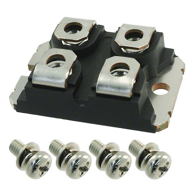
As an example this unit is massive overkill for a fuel pump, but it's large, uses screw terminals, will drop only 40mv at 40A, and will pretty much never die. It can handle 480 amps continuously, and is basically made of heat-sink (not that it'll matter, as 40A will only produce about 1.7 watts across it.)
http://www.digikey.com/product-detai...5T2-ND/2217438
That's an extreme example, of course. If you don't mind doing a little PCB work, you can just as easily use a more reasonably-sized part, such as this: http://www.digikey.com/product-detai...8-5-ND/1039564
Last edited by Joe Perez; 02-04-2016 at 04:33 PM.
Reply
0
0
05-03-2016, 09:21 PM
#39
SADFab Destructive Testing Engineer
iTrader: (5)
Join Date: Apr 2014
Location: Beaverton, USA
Posts: 18,642
Total Cats: 1,866
Revisiting PWM. I want simple plug and play. So I'm going with the Hella relay ben mentioned. I have seen a few places that it is just a mosfet, but it has a nice package and is physically compatible with standard relay sockets.
Hella Relays H41773001 - Free Shipping on Orders Over $99 at Summit Racing
This is my plan, please correct me if anything seems wrong.
The standard miata fuel pump relay is a positive control relay, which uses the AFM 12v signal. Which we jump at the AFM connector. And then the megasquirt output grounds the relay.
This will be different. I will still use the signal from the megasquirt, but I will jump the wire from the megasquirt directly to the fuel pump wire that goes to the tank. That will give me a signal wire for the solid state relay.
The relay will be wired directly to the battery and fuel pump with 10 gauge wire.
I will use the open loop pwm control. Find the minimum duty cycles that I can hit my desired fuel pressure at, and then add a bit of duty cycle to be on the safe side.
Reply
0
0


