
Fuel Pump Voltage Drop vs Pressure 1999
 03-16-2015 | 04:13 AM
#1
Thread Starter
Elite Member
iTrader: (16)
Joined: Aug 2007
Posts: 9,352
Total Cats: 524
From: Houston, TX
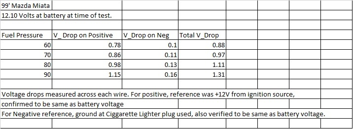
Did this test today, results below. I measured the voltage drop on each wire. Looks like the wires are too skimpy for my 255HP.

Reply
 0
0

0

 03-16-2015 | 10:20 AM
#3

Joined: Sep 2005
Posts: 33,556
Total Cats: 6,933
From: Chicago. (The less-murder part.)
I'd be really curious to know how much of that 1v drop on the supply side is occurring across the fuel pump relay itself. As Ted75zcar noted, 1v drop on a 12v supply is massive, especially for something as nominally trivial as a fuel pump motor.
Do you have access to a DC ammeter capable of reading several amps?
Do you have access to a DC ammeter capable of reading several amps?
Reply
0
0
03-16-2015 | 11:03 AM
#4
Joined: Jan 2013
Posts: 5,012
Total Cats: 859
From: Seneca, SC
I suppose, since you made the measurements, it is likely that you are planning to jack the pressure up. If not:
The stock FPR is set at 60 psi, so that is where the operating point of the pump is. Flow goes either into engine, or back into tank. Very nearly a steady state proposition from the pump and wiring point of view.
The stock FPR is set at 60 psi, so that is where the operating point of the pump is. Flow goes either into engine, or back into tank. Very nearly a steady state proposition from the pump and wiring point of view.
Reply
0
0
03-16-2015 | 12:34 PM
#5
Thread Starter
Elite Member
iTrader: (16)
Joined: Aug 2007
Posts: 9,352
Total Cats: 524
From: Houston, TX
I'd be really curious to know how much of that 1v drop on the supply side is occurring across the fuel pump relay itself. As Ted75zcar noted, 1v drop on a 12v supply is massive, especially for something as nominally trivial as a fuel pump motor.
Do you have access to a DC ammeter capable of reading several amps?
Do you have access to a DC ammeter capable of reading several amps?
Looks like relay is under the dash.... Not sure I want to go digging for it to measure voltage drop across it.
Just checked walbro specs though
60 PSI = 10A current
90 PSI = 12A current.
I think the fuel/pump has 16 gauge wire going to it.
This calculator: American Wire Gauge table and AWG Electrical Current Load Limits with skin depth frequencies and wire breaking strength
Shows, with 12 ft of wire, at 12V
10A =1 V drop
12A = 1.2V drop
So not that far off.
Reply
0
0
03-17-2015 | 12:25 AM
#6
Well, I guess the numbers add up then.
Just more incentive to build a high-current input spanning switch mode converter. The non-linearity that is tolerated in automotive electrical systems just baffles me.
I imagine you are probably going to install a higher gauge feed. I think if I was going that route I would probably drive a secondary relay at the pump using the existing control signal. That way you can wire directly from the battery with the larger conductor, but you don't have to run it back and forth.
I suspect this is discussed at length somewhere around here.
Dig the SC build by the way, I am in the process of piecing together my own compound ... even though everybody tells me not to do it
Reply
0
0
03-17-2015 | 09:36 AM
#7
Joined: Sep 2005
Posts: 33,556
Total Cats: 6,933
From: Chicago. (The less-murder part.)
Here we are in the 21st century, and our few EVs still have 12v electrical systems to drive all their conventional accessories.
Reply
0
0
03-17-2015 | 01:51 PM
#8
Thread Starter
Elite Member
iTrader: (16)
Joined: Aug 2007
Posts: 9,352
Total Cats: 524
From: Houston, TX
Well, I guess the numbers add up then.
Just more incentive to build a high-current input spanning switch mode converter. The non-linearity that is tolerated in automotive electrical systems just baffles me.
I imagine you are probably going to install a higher gauge feed. I think if I was going that route I would probably drive a secondary relay at the pump using the existing control signal. That way you can wire directly from the battery with the larger conductor, but you don't have to run it back and forth.
I suspect this is discussed at length somewhere around here.
Dig the SC build by the way, I am in the process of piecing together my own compound ... even though everybody tells me not to do it
Just more incentive to build a high-current input spanning switch mode converter. The non-linearity that is tolerated in automotive electrical systems just baffles me.
I imagine you are probably going to install a higher gauge feed. I think if I was going that route I would probably drive a secondary relay at the pump using the existing control signal. That way you can wire directly from the battery with the larger conductor, but you don't have to run it back and forth.
I suspect this is discussed at length somewhere around here.
Dig the SC build by the way, I am in the process of piecing together my own compound ... even though everybody tells me not to do it
Reply
0
0
 02-03-2016 | 05:36 PM
#10
Thread Starter
Elite Member
iTrader: (16)
Joined: Aug 2007
Posts: 9,352
Total Cats: 524
From: Houston, TX
I ran a 40A fuse to the battery, 10 gauge wire, 50A relay, and 10 gauge wires into the tank. 10 Gauge ground to chassis just outside of tank on the shelf. Voltage drop of 0.02-0.03 with twin walbro 255's. I now have a Walbro 450 and a Walbro 255, didn't measure it again but it's negligible with the new wiring.
Reply
0
0
 02-03-2016 | 07:10 PM
#12

Joined: Apr 2014
Posts: 18,642
Total Cats: 1,866
From: Beaverton, USA
I'm using the racetronix adapter thingy. Got it on sale over black friday.
Racetronix - Universal Bulkhead Wiring System, 4-Way
Racetronix - Universal Bulkhead Wiring System, 4-Way
Reply
0
0
 02-03-2016 | 07:26 PM
#16
Joined: Apr 2014
Posts: 18,642
Total Cats: 1,866
From: Beaverton, USA
Thats what i was assuming you were going to do. 2 power 2 ground.
Pat where did you ground outside the tank?
You could even use the 2 stock wires too if you wanted all of the wires.
Make sure you get the racetronix e85 plug/install kit for the walbro450
Pat where did you ground outside the tank?
You could even use the 2 stock wires too if you wanted all of the wires.
Make sure you get the racetronix e85 plug/install kit for the walbro450
Reply
0
0
02-03-2016 | 08:15 PM
#18
Joined: Sep 2005
Posts: 33,556
Total Cats: 6,933
From: Chicago. (The less-murder part.)
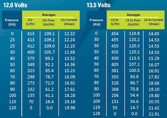
Then I saw the chart which deezums posted.
Holy ****. 21A at 13.5V is 280 watts, which is a pretty substantial heating element. Granted, not a lot of us are running 110 PSI on the fuel rail at all times, but that's still amazing. Put three 100w light bulbs next to each other on your desk and turn them on, then see how long you can hold your hand over them.
Then put that in your fuel tank.
Then add 60% (for the other pump).
Reply
0
0
02-03-2016 | 08:20 PM
#19

We've known since 1999 that the stock wiring is inadequate for the stock fuel pump -- How is this news in 2016?
For a 20A pump driven by the battery via relay, you'll want a minimum of 12ga wiring. If you were gangster, you'd use a spare PWM output to duty cycle that big *** fuel pump at low loads. Easy breezy with a solid state relay.
For a 20A pump driven by the battery via relay, you'll want a minimum of 12ga wiring. If you were gangster, you'd use a spare PWM output to duty cycle that big *** fuel pump at low loads. Easy breezy with a solid state relay.
Reply
0
0
02-03-2016 | 08:21 PM
#20
I was about to say "40A? Jesus, why not just measure the actual current and then size accordingly, rather than build a bomb right behind the driver's seat?"
Then I saw the chart which deezums posted.
Holy ****. 21A at 13.5V is 280 watts, which is a pretty substantial heating element. Granted, not a lot of us are running 110 PSI on the fuel rail at all times, but that's still amazing. Put three 100w light bulbs next to each other on your desk and turn them on, then see how long you can hold your hand over them.
Then put that in your fuel tank.
Then add 60% (for the other pump).
Reply
0
0


