FML, cut the wrong trace installing revlimiter gauges. help with repair?
 01-19-2015, 02:11 PM
#1
Senior Member

Thread Starter
Join Date: Nov 2005
Location: Baltimore Maryland
Posts: 1,038
Total Cats: 9
Ok, as is well documented, I am in fact an idiot (especially when it comes to electrical things) and I cut a trace in my gauge cluster circuit board in a place where I should not have.
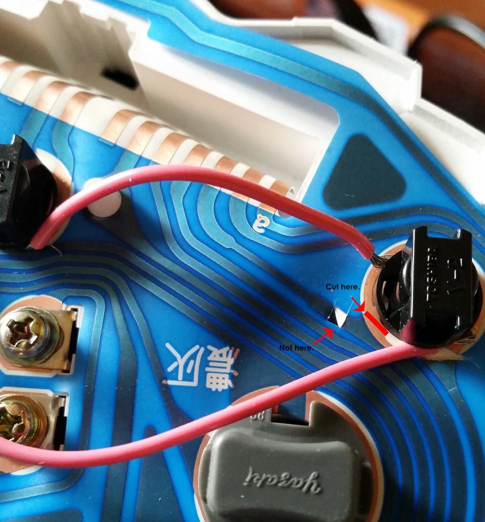
Any help fixing this mistake would be wonderful, as now my tachometer only functions with my headlights turned on :(
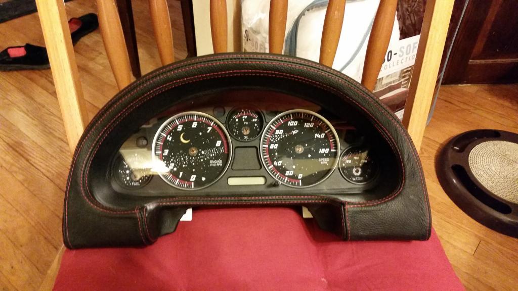
On the bright side, the gauges look amazing and I was able to successfully install my leather gauge hood cover from Redlinegoods, as well as their door pulls.

Any help fixing this mistake would be wonderful, as now my tachometer only functions with my headlights turned on :(
On the bright side, the gauges look amazing and I was able to successfully install my leather gauge hood cover from Redlinegoods, as well as their door pulls.


Reply
 0
0

0
 01-19-2015, 03:00 PM
#6
Senior Member
Thread Starter
Join Date: Nov 2005
Location: Baltimore Maryland
Posts: 1,038
Total Cats: 9
Do you guys think a window defroster repair kit will do it? I can't solder for ****, and a hamfisted attempt could result in me needing a whole new cluster. Wouldn't the window defroster repair method result in eventual damage to the plastic it would lay in due to the current, or an eventual short?
Reply
0
0
01-19-2015, 07:31 PM
#10
Boost Pope

iTrader: (8)
Join Date: Sep 2005
Location: Chicago. (The less-murder part.)
Posts: 33,339
Total Cats: 6,793
This should not be a concern. The amount of current drawn by the tachometer is miniscule, and the length of the repair very short. Heat generation would be on the order of a few milliwatts, if even that.
Reply
0
0
01-19-2015, 08:32 PM
#11
Senior Member
Thread Starter
Join Date: Nov 2005
Location: Baltimore Maryland
Posts: 1,038
Total Cats: 9
Adam, thanks for your quick reply! I'm just asking somewhere that I know we have some people experienced with this stuff for a second opinion. I have some of the defroster repair liquid in my possession and I'll attempt the repair tomorrow morning when I get home from work (night work stinks btw) I figure that it's the least intrusive method so I'll begin with it!
Thanks for all the help guys, I'll keep everyone updated!
Thanks for all the help guys, I'll keep everyone updated!
Reply
0
0
01-20-2015, 12:21 PM
#12

You can buy a spare NB1 gauge cluster for $35-$45 shipped and just swap the gauges and odometer into the new housing if all else fails.
I dont know why Adam says to cut those traces. I just put a piece of insulating tape under where the light would make contact and route a new wire there. Totally reversible and less chance of messing it up.
I was able to solder a tiny wire to the leads, but I wouldn't recommend it as I burned up a couple traces on a test flex circuit before succeeding.
Reply
0
0
01-20-2015, 07:07 PM
#13
Senior Member
Thread Starter
Join Date: Nov 2005
Location: Baltimore Maryland
Posts: 1,038
Total Cats: 9
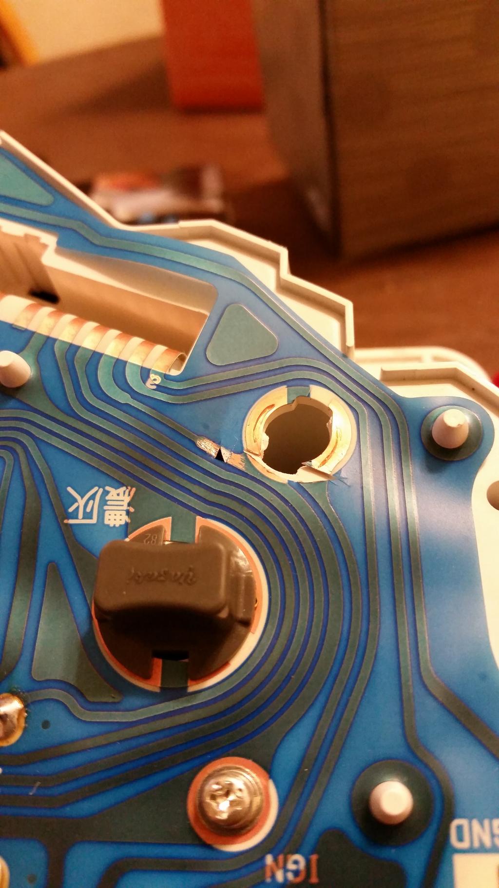
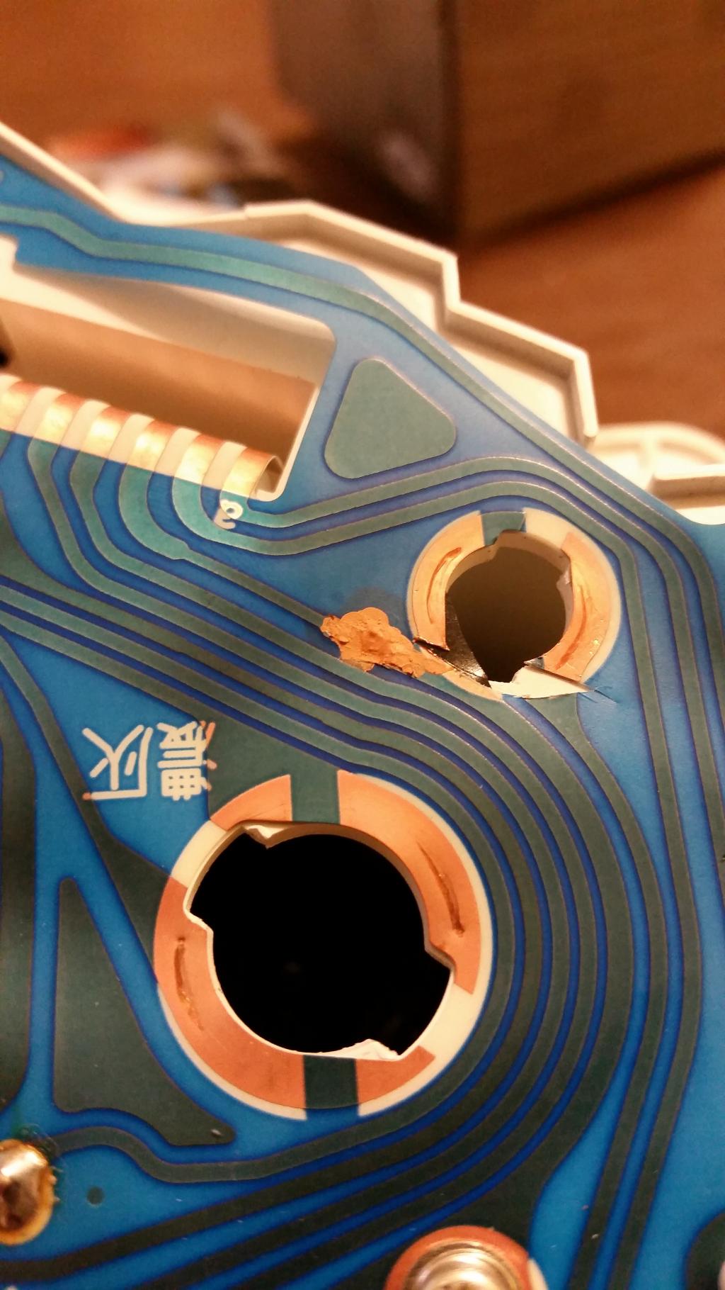
Ok! I think I have it taken care of but have to test the continuity of the trace to be sure. Here are some pics of what I did, sorry it ended up messy, but it doesn't have to be pretty to work on the backside!
first, I had to scrape away some of the plastic, and noticed that there was a void under where I had originally cut.
I filled the gap by attaching a small piece of electrical tape to the cluster itself. In hindsight it may have been a better idea to attach it to the underside of the flex board, that would have solved the next issue I came across.
I tried to tape the trace up and be neat about things, but when I tried to remove the tape (even though I barely tacked the tape down) it would pull the repair away from the tape on the cluster since the board itself moved.
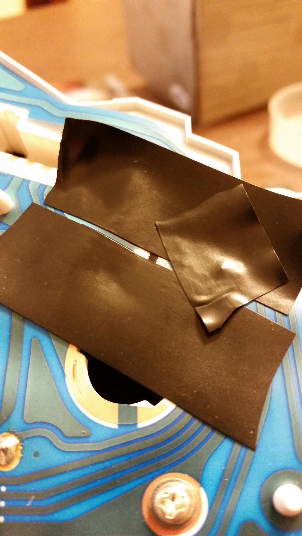
Here is the finished produc. I'm not proud of how it looks, but if it works, I'm happy!
first, I had to scrape away some of the plastic, and noticed that there was a void under where I had originally cut.

I filled the gap by attaching a small piece of electrical tape to the cluster itself. In hindsight it may have been a better idea to attach it to the underside of the flex board, that would have solved the next issue I came across.
I tried to tape the trace up and be neat about things, but when I tried to remove the tape (even though I barely tacked the tape down) it would pull the repair away from the tape on the cluster since the board itself moved.

Here is the finished produc. I'm not proud of how it looks, but if it works, I'm happy!

Reply
0
0

Thread
Thread Starter
Forum
Replies
Last Post
StratoBlue1109
Miata parts for sale/trade
21
09-30-2018 01:09 PM
stoves
Suspension, Brakes, Drivetrain
5
04-21-2016 03:00 PM


