

The custom fabrication thread! (Post pics of stuff you have made)


 07-24-2014, 12:40 PM
#804
mkturbo.com


iTrader: (24)
Join Date: May 2006
Location: Charleston SC
Posts: 15,193
Total Cats: 1,685
The actual welding of the tophats took about an hour, letting them cool off was the longest part. Getting the to that point was a pita because we did not have the proper tools. No clue how much time my friend actually spent cutting off the top of the stock tophat.

Reply
 0
0

0
 07-24-2014, 02:41 PM
#807
Elite Member
iTrader: (8)

Join Date: Dec 2008
Location: Kingston, Ontario
Posts: 2,910
Total Cats: 51
If you have a drill press, a hole saw and a welder, it would be super easy.
Drilling the caps out would take 10 minutes, prepping for weld would be about 15-20 minutes and welding them up would take about 20 minutes
Drilling the caps out would take 10 minutes, prepping for weld would be about 15-20 minutes and welding them up would take about 20 minutes
Reply
0
0
 07-27-2014, 02:18 PM
#809

Having 2 Miatas and being a track addict, I seem to be assembling more engines than I used to. One part of assembly that was always a bit of a pain was torqueing the flywheel and crankshalf pulley bolts. Mazda has a SST (Special Service Tool) that locks the flywheel for this purpose. So, made my own out of some 1.25" angle iron. Pictures speak for themselves. I did the rivets and then went ahead and hit it with a welder. I don't know if rivets alone would have been sturdy enough.
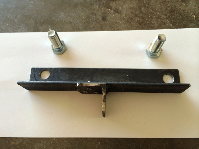
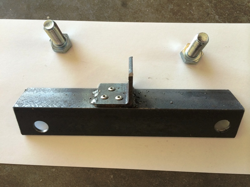
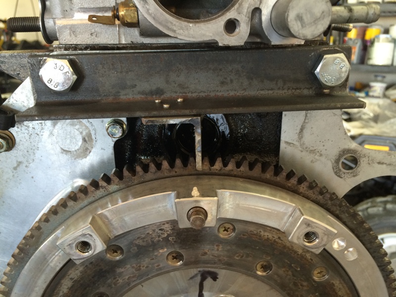
Works great!
Works great!
Reply
0
0
07-27-2014, 02:25 PM
#810
Cpt. Slow
iTrader: (25)
Join Date: Oct 2005
Location: Oregon City, OR
Posts: 14,429
Total Cats: 1,207
Just use two of the tranny bolts, thread one in to that top hole, and jam another against the bolt and a flywheel tooth. Works like a charm, and you don't have to find or have your tool.
Reply
0
0
07-27-2014, 03:14 PM
#812
Cpt. Slow
iTrader: (25)
Join Date: Oct 2005
Location: Oregon City, OR
Posts: 14,429
Total Cats: 1,207
Yup, your tool is nice though.
Just have a socket for the pressure plate bolts ready, hold the bolt with one hand, and turn the flywheel with the socket on one of the pp bolts until the bolt is jammed against the other.
Just have a socket for the pressure plate bolts ready, hold the bolt with one hand, and turn the flywheel with the socket on one of the pp bolts until the bolt is jammed against the other.
Reply
0
0
07-27-2014, 09:11 PM
#814
mkturbo.com
iTrader: (24)
Join Date: May 2006
Location: Charleston SC
Posts: 15,193
Total Cats: 1,685
That is what I would figure also. Here is the story of the top hats. My friend wanted them welded up. He said he would be over one night with the stuff to be welded. I expected him to show up and have the top hats in hand with the pipes ready to roll. He shows up with the top hats still on the car. So had to remove them from there. He did bring a hole saw, but it was a shitty one and I only have a HF $9.99 drill. So drilling through them did not work well. They then took them to a friends house with a drill press. Unfortunately the hole saw was to messed up to make the cut. He took the top hats to his school and tried with a big *** drill press. Not sure why that failed. He then used some other tool and got the to hats into two pieces. The cuts were horrible and not very evenly around. So I did the best I could with what I was given on the welding.
Reply
0
0

 07-28-2014, 11:44 AM
#818

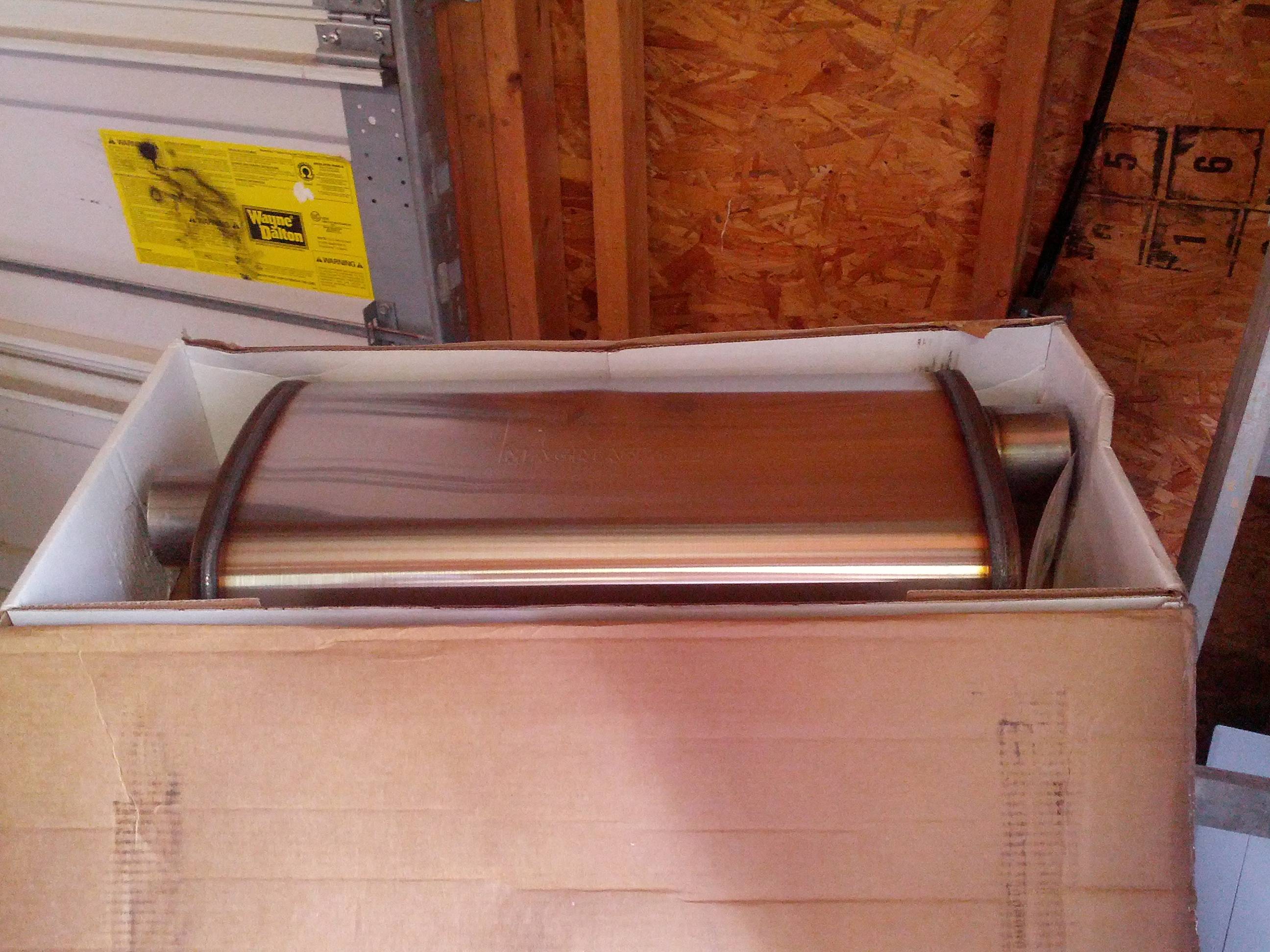
A different kind of fab, but I thought you all might enjoy it.
I bought a JDM 6-speed cluster for my NB.
I found that when using a US odometer unit, the speedometer wouldn't read right because the JDM speedometer tops out at around 190kph while the US speedometer is 260kph. The odometer drives the needle by angle, so it ended up being about 22% off from a true reading.
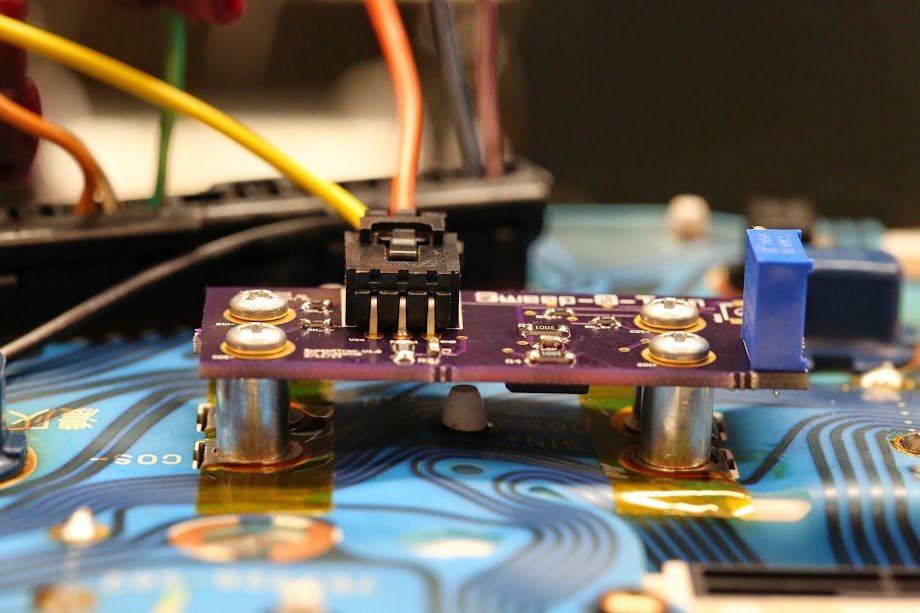
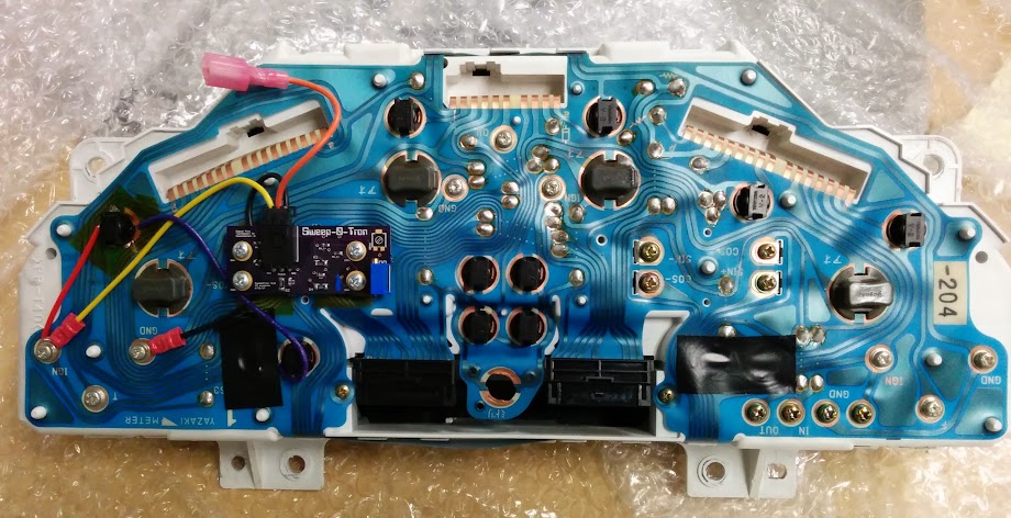
I taught myself some electronics and designed and built a custom circuit board that allows arbitrary scaling of the speedometer or tachometer. It reads the raw tach/vss signal from the cluster via a T-tap but doesn't require any permanent modification to the cluster. It's actually more accurate and has a faster response time than the stock gauges. On my cluster, I set it up to read mph rather than kph, so it's now a 180mph speedometer
The circuit is relatively simple: it implements a standalone air core motor driver and has a trimpot to fine-tune the scale while under way. It took about three board layout revisions to get the design perfect, but it works great now. On my cluster, I was able to get it within +/-1mph from GPS speed reading.


I bought a JDM 6-speed cluster for my NB.
I found that when using a US odometer unit, the speedometer wouldn't read right because the JDM speedometer tops out at around 190kph while the US speedometer is 260kph. The odometer drives the needle by angle, so it ended up being about 22% off from a true reading.
I taught myself some electronics and designed and built a custom circuit board that allows arbitrary scaling of the speedometer or tachometer. It reads the raw tach/vss signal from the cluster via a T-tap but doesn't require any permanent modification to the cluster. It's actually more accurate and has a faster response time than the stock gauges. On my cluster, I set it up to read mph rather than kph, so it's now a 180mph speedometer
The circuit is relatively simple: it implements a standalone air core motor driver and has a trimpot to fine-tune the scale while under way. It took about three board layout revisions to get the design perfect, but it works great now. On my cluster, I was able to get it within +/-1mph from GPS speed reading.
Reply
4
4
07-29-2014, 11:53 PM
#819
Elite Member
iTrader: (8)
Join Date: Dec 2008
Location: Kingston, Ontario
Posts: 2,910
Total Cats: 51
I'll post a picture here that I posted in my personal fab thread. Check out the rest of the work in my thread if you havent already.
 HellaFab Miata Vband bottom mount manifold by HellaFab, on Flickr
I have an EFR manifold coming up next.
HellaFab Miata Vband bottom mount manifold by HellaFab, on FlickrI have an EFR manifold coming up next.
Reply
0
0


