When you click on links to various merchants on this site and make a purchase, this can result in this site earning a commission. Affiliate programs and affiliations include, but are not limited to, the eBay Partner Network.
Voltage control options - NA with 1.8VVT swap and MS3PRO
First, big thanks to all that contributed to the VVT swap mega thread. I did a successful 04’ engine swap last year. It was my first engine swap ever on any platform and it sure feels good. It’s also my first foray in standalone engine tuning which brings me to my first question that I hope may help someone doing this swap in the future that finds themselves in this same pickle, albeit a slightly unique one.
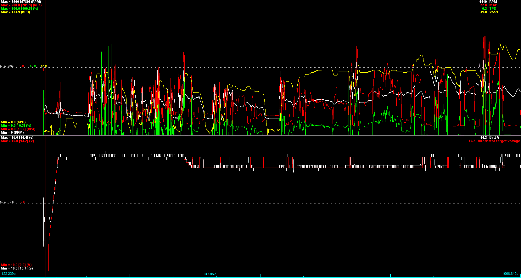
Let’s talk alternator control, voltages and dead time. I followed the instruction and swapped out the NB2 alternator with an internally regulated NA alternator. I’ve ran into issues with the NA alternator since I have the stock gauge cluster removed. Apparently the there is a battery light + a resistor(s) built into the dash that is part of the alternators circuit that coaxes the regulator to do its thing at start up, but when removed, the car runs on straight battery (~12.2V) until the RPMs get above 2500 RPMS or so to “wake up” the voltage regulator. I’ve confirmed this looking at MS logs before and after I removed the stock cluster. I’ve also noticed that I have fairly significant voltage swings during the course of a track day (~14.8 – 15.4V on track). All this make for fuel tuning a bit of a challenge since this can affect dead time as voltages change. Of course this can be compensated for by adjusting the dead time voltage curve but I feel this process can be simplified by making sure voltages stay tight. Since the MS3PRO PNP has built in what seems to be rock solid Alternator Control, I’m toying with the idea of ditching the NA alternator and putting the 04’ NB alternator back in. I’m a bit aside myself on what the best solution here is:
a) Retain the NA alternator and try to find a way to trick the regulator the cluster is still installed.
b) Running voltages are fine, stop being a bitch and adjust the dead time voltage curve accordingly and just deal with the car idling on battery power until the regulator wakes up.
c) Possibly make tuning much easier by utilizing the built in voltage regulation of the MS3PRO and the much tighter voltage range that ECU regulation could afford.
Technically all three of these options will require a revisit to the dead time voltage curves, I just want to make sure I’m not compensating too much in the curve because the electrical system can be regulated better.
Hopefully someone on here has already messed with MS3PRO alternator control as of late and can give me some insight. All the threads I've found are from when they first introduced the functionality ~10 years ago.
I've done a VVT swap into an 1990 same as you except I'm using an MS3x instead of the Pro. I opted to go with the NB alternator and controlled it with the ECU. Since I didn't have AC I used the circuit for alternator control since the connector the circuit was on was quite close and meant I didn't have to run extra wires through the firewall.
Control is very steady and also has the benefit of allowing you to adjust a charging start delay, ramp on time, and different voltages for initial charge time, normal run mode, overrun and WOT. It also might make it easier to adjust injector dead times since you could change the charging voltage and check the AFR isn't affected. I haven't tried this though.
Apparently the there is a battery light + a resistor(s) built into the dash that is part of the alternators circuit that coaxes the regulator to do its thing at start up, but when removed, the car runs on straight battery (~12.2V) until the RPMs get above 2500 RPMS or so to “wake up” the voltage regulator.
Huh, TIL. I had realized my startup voltage was quite low, but I hadn't correlated that with ditching the stock cluster. I just figured it was my questionable alternator on the way out.
I've done a VVT swap into an 1990 same as you except I'm using an MS3x instead of the Pro. I opted to go with the NB alternator and controlled it with the ECU. Since I didn't have AC I used the circuit for alternator control since the connector the circuit was on was quite close and meant I didn't have to run extra wires through the firewall.
Control is very steady and also has the benefit of allowing you to adjust a charging start delay, ramp on time, and different voltages for initial charge time, normal run mode, overrun and WOT. It also might make it easier to adjust injector dead times since you could change the charging voltage and check the AFR isn't affected. I haven't tried this though.
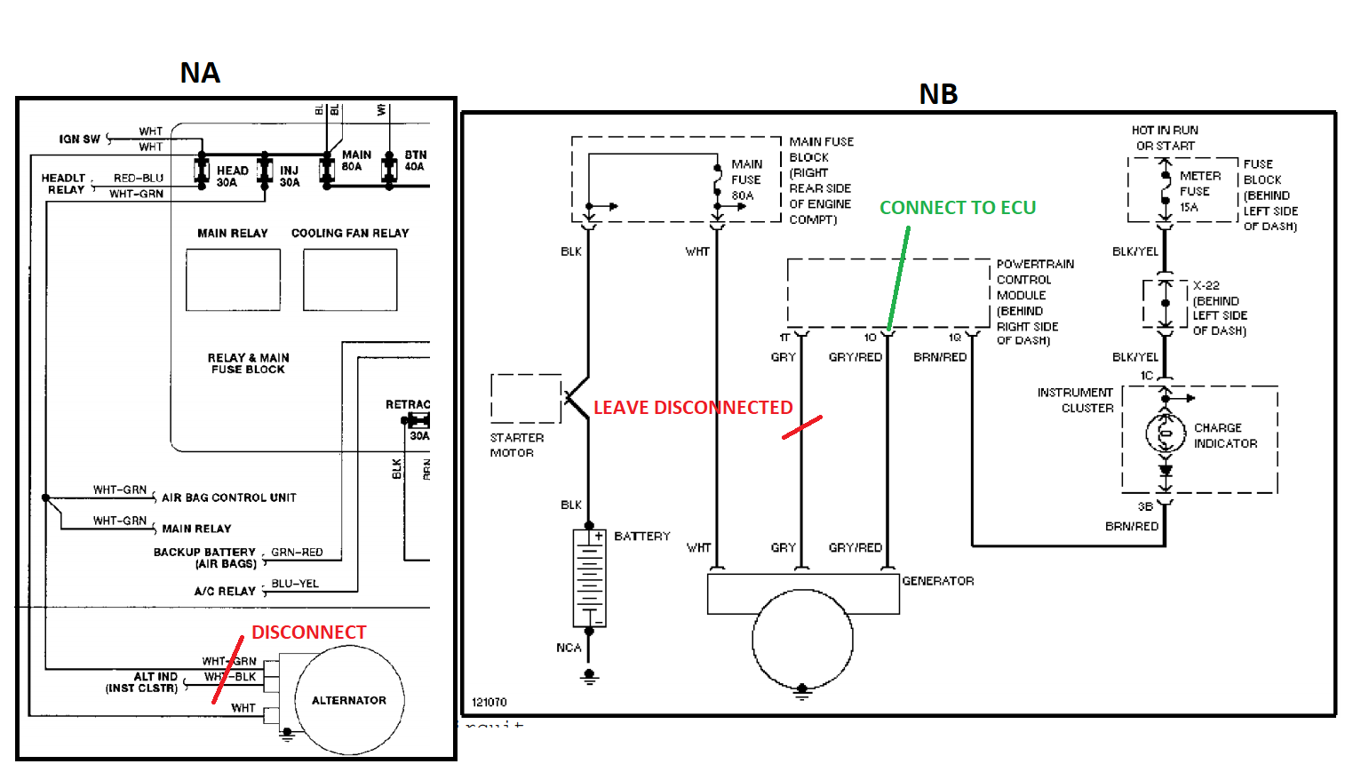
That looks really good, thanks for sharing. Would you mind hand holding me a bit in regards to how you wired this all up? I don't want to mess this up because the consequences would be no bueno. The MS3PRO PNP has a preset I/O for alternator field control (PWM3). I'm not sure where this wire needs to go with the NB alternator. The only thing I'm sure of is where the white wire goes:
Huh, TIL. I had realized my startup voltage was quite low, but I hadn't correlated that with ditching the stock cluster. I just figured it was my questionable alternator on the way out.
Figured if anyone ran into this issue it would be the Spec Miata folks since cluster removal is pretty routine. Apparently this is fairly common with a lot of cars in the 90's. Didn't take much searching before I confirmed my suspicions. It applies to the internal regulated cars only, not ECU regulated. Spec Miata Community: Gauge cluster replacement?
Wiring it is pretty simple. The white power feed ring terminal obviously goes in the same spot. The other connector with two pins is left disconnected since it just has a switched 12V and the battery warning lamp circuit which isn't required on the NB alternator.
Just need to connect the field terminal (grey/red) circuit to the NB alternator to enable control. I believe the other circuit is a feedback from the generator which MS doesn't require. For anyone also using the OEM dash you'll probably also want to run an output from the ECU to the dash to control the warning lamp as well. You'll also need to check that the output you are using will send a 0-5V PWM signal out to the alternator. You may need to add a pull-up resistor on the PNP Pro.
Gods work Thanks Barton. Found some initial tunerstudio settings on MiataTurbo, can't wait to try it out.
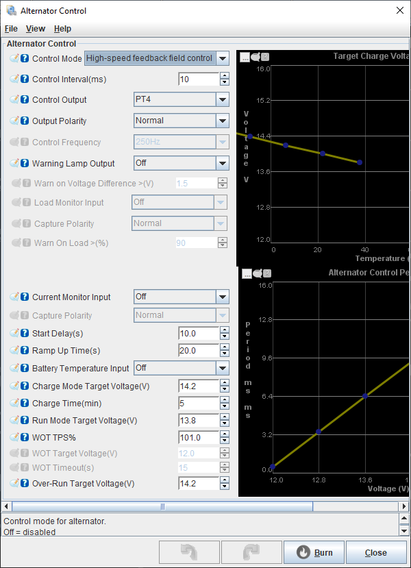
These are the settings I use for mine. The control output pin will be different depending on which you select to wire up to the alternator and it will also determine the output polarity. If the polarity is incorrect the control will operate incorreclty raising the voltage when it tries to lower or the other way around. You can use the test mode and a multi-meter to determine the correct polarity required.
Another thing to check is if there's a voltage difference between what the ECU sees and the alternator output. It's possible to have a voltage drop on the ECU supply circuit causing it to read a lower voltage than the alternator output (I had almost a 1V drop before I re-wired the fuel pump to it's own relay). This could mean you'll see your target voltage at the ECU but the actual output will be higher possibly overcharging the battery.
Another thing to check is if there's a voltage difference between what the ECU sees and the alternator output. It's possible to have a voltage drop on the ECU supply circuit causing it to read a lower voltage than the alternator output (I had almost a 1V drop before I re-wired the fuel pump to it's own relay). This could mean you'll see your target voltage at the ECU but the actual output will be higher possibly overcharging the battery.
Thanks for the tip, did not consider checking that! What caused the voltage drop? Just too many components on the same circuit with the OEM wiring?
I've replaced the NB1 alternator in my 99 with a RX-7 alternator (similar to the NA alternator, but with higher output). You're right, the self-regulated NA (or RX-7) alternator won't "turn on" until the first time it sees the RPM's go about 1500-1700). There is a "trick" that I've used for several years now, and that is to wire a switch in the cockpit to 12V, and then have that go to the "S" terminal on the alternator. The "S" terminal is the signal for the "field excite" on the alternator - that is what "turns on" the regulation. So, I start with engine with the 12v applied, the regulator turns on, then I can turn off the switch and voltage regulation happens like normal. I've been doing it this way for 6 or so years not and haven't looked back.
You'll have to Google which of the terminals on the NA alternator is the "S" terminal, but that shouldn't be too hard.
That's another really good option. Since my fancy-shmancy ECU has Field Control I want to give that a shot first, if no dice, this is a good back up solution.
You can use the test mode and a multi-meter to determine the correct polarity required.
Gonna have to ask for you to dumb things down a little for me again. I know where the test modes are at in TunerStudio but what kind of behaviors will I be looking for in the multimeter to determine polarity? Hoping to tackle this this weekend...
If the output is 0V when off and 5V when on then the output polarity is 'normal'. If the output is 5V when off and 0V when on then the output is inverted.
Just a quick update on this, I got this working, however I have not tested it on the track yet under heavy loads. At idle at least, it works great and holds steady and hits the values indicated in TS + or - 0.1V. I did wire in a 1K pull down resistor of the 5v ref on the MS from the recommendation of the excellent customer support at DIYAutoTune. Not sure if it was necessary but did it anyway.
Now that I have a MS3PNP Pro I am revisiting this thread in hopes that I can actually control my alternator. So stop me before I burn my car to the ground...
I have read this thread (and others) regarding connecting the grey/red alternator field wire to the MS. When I look at the diagram above from BimmerSchnitzel my spidey senses went off. "2I" on connector 2 for the alternator field can't be right! After a couple of days of digging and causing myself lots of confusion I realized...his diagram was based on a 90/93 MS3PNP whereas my MS3PRO is for a 99/00 (see the difference below). The pinout on the left is for the 90/93 and the one on the right is for the 99/00;
That being the case, I should be connecting 1O to the alternator field instead of 2I, correct? The location of the 5V reference is in the same place on Connector 3, so that much is fine. So all I have to do is to connect the 5V through a 1K resistor (I saw some other posts that suggested that 1K might be too much and that 460 would be sufficient - any comments?) and all will be right with the world and I can enjoy regulated voltage from now on.
Well, in lieu of any responses I gave it the old college try and...drum roll...nothing. Volts out of the alternator are un-regulated. So that leads me to one of three conclusions;
The internal regulator and/or field windings on the alternator are borked. A likely outcome seeing as how it's been running in this unregulated state since time immemorial.
I have attached the 1O output line from the MS onto the wrong terminal on the alternator. Again, likely as I've screwed around with that connector and associated wire so much that I can't easily remove the connector without taking the whole damned alternator out of the car, which makes inspection of that line practically impossible in-situ.
I don't know what the hell I'm doing. Again, very likely since me and electricity have a long standing love/hate relationship.
So, what do I do? I already ordered a new(-ish) alternator - yeah, yeah, yeah, aftermarket ne-manufactured Chinese crap blah, blah, blah - and give that a whirl. That will allow me to A/B the effectiveness of the internal regulator with a "brand-new" specimen. AND it will allow me to inspect/correct whether I have the right terminal on the alternator connected to the field control line. That will only leave my incompetence as the final barrier to fully controlled alternator nirvana.
If it's the voltage regulator you can also replace that, part is cheap and comes with new carbon brushes(<20$). While at it you could also replace both bearings.
Not a hard job to rebuild the alternator.
If it's the voltage regulator you can also replace that, part is cheap and comes with new carbon brushes(<20$). While at it you could also replace both bearings.
Not a hard job to rebuild the alternator.
Yeah, I thought about that but I'm taking this plan of attack;
Put in the reman alternator as-is and see if it works. If so, I win.
If the new alternator doesn't regulate, check the wires to make sure that I'm sending the (pulled-up) signal from 1O to the field control. If I had that wired wrong and the new alternator regulates after correction, I win.
Just for ***** and giggles, go to a 12V pull-up instead of the weakling 5V. It that works, I win.
Take the old alternator to O'Really's and have it tested. If the regulator in it is toast, re-build it [cue Six-Million Dollar Man music] and make it better. That way I have a spare and my growing pile of spares has a new tenant.
If none of the above works admit defeat, get an external voltage regulator and drive away in shame.
I'm picking up the alternator tonight and it's going in on Saturday.
Just for the record - and to close the story on my thread hijack - here's what has happened...
After wondering why everything I was trying had zero effect i came to a "D'oh moment" where I realized that I was NOT dealing with a NB1 alternator (where the voltage is controlled via the ECU), but I had swapped in the alternator from a FD RX-7 years ago (which has a internal regulator). So, attempting to use the MS3 to regulate voltage was NEVER going to work. What I discovered was that all I needed was a switched 12V line to the "L" terminal and a 12V line through a resistor and a diode to the "S" terminal and...Voila!...regulated voltage!
So, word to the wise; before "polluting" a thread with irrelevant inputs, understand your setup.


 01-27-2021, 08:18 PM


 0
0


 Thanks Barton. Found some initial tunerstudio settings on MiataTurbo, can't wait to try it out.

 I know where the test modes are at in TunerStudio but what kind of behaviors will I be looking for in the multimeter to determine polarity? Hoping to tackle this this weekend...