

Thread for naturally aspirated manifold design
 01-02-2016, 07:25 PM
#61
Senior Member

Thread Starter
iTrader: (1)

Join Date: Jul 2012
Location: durham NC
Posts: 792
Total Cats: 143
Corrosion is pretty easily solved with a layer of fiberglass between the carbon and the aluminum.
I also did some reading on bonding carbon to aluminum when there is a potential for high temps. People are suggesting a larger bonding gap and a silicone adhesive. Regardless, this can be solved by some form of fasteners, rivets, or other mechanical interlock between the parts. The manifold itself should be really light with the majority of the weight in the throttle body. If I need to add more strength and stiffness to the part I can laminate balsa wood triangles between the plenum and underside of the runners to add some fibers more in line with the stresses.
I also did some reading on bonding carbon to aluminum when there is a potential for high temps. People are suggesting a larger bonding gap and a silicone adhesive. Regardless, this can be solved by some form of fasteners, rivets, or other mechanical interlock between the parts. The manifold itself should be really light with the majority of the weight in the throttle body. If I need to add more strength and stiffness to the part I can laminate balsa wood triangles between the plenum and underside of the runners to add some fibers more in line with the stresses.

Reply
 0
0

0
01-02-2016, 07:52 PM
#62
Junior Member

Join Date: Jan 2015
Posts: 272
Total Cats: -25
Corrosion is pretty easily solved with a layer of fiberglass between the carbon and the aluminum.
I also did some reading on bonding carbon to aluminum when there is a potential for high temps. People are suggesting a larger bonding gap and a silicone adhesive. Regardless, this can be solved by some form of fasteners, rivets, or other mechanical interlock between the parts. The manifold itself should be really light with the majority of the weight in the throttle body. If I need to add more strength and stiffness to the part I can laminate balsa wood triangles between the plenum and underside of the runners to add some fibers more in line with the stresses.
I also did some reading on bonding carbon to aluminum when there is a potential for high temps. People are suggesting a larger bonding gap and a silicone adhesive. Regardless, this can be solved by some form of fasteners, rivets, or other mechanical interlock between the parts. The manifold itself should be really light with the majority of the weight in the throttle body. If I need to add more strength and stiffness to the part I can laminate balsa wood triangles between the plenum and underside of the runners to add some fibers more in line with the stresses.
Reply
-2
-2
01-03-2016, 11:38 AM
#63
Senior Member
Thread Starter
iTrader: (1)
Join Date: Jul 2012
Location: durham NC
Posts: 792
Total Cats: 143
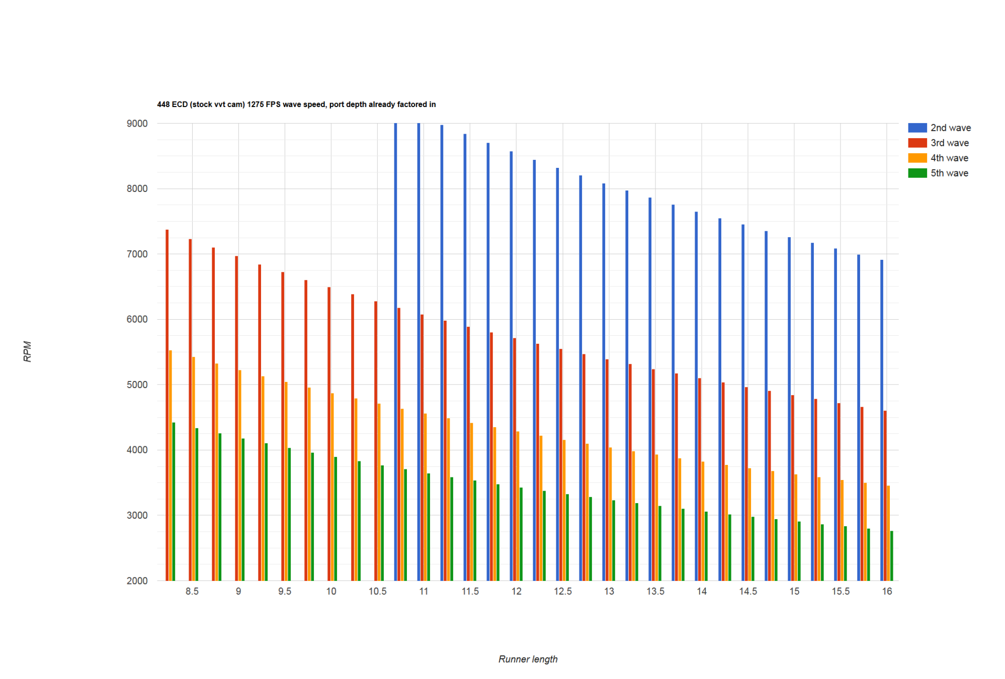
I improved my spread sheet and made a big graph. The two major variables are posted in the title (ECD and wave speed). I am current reading a bunch of different FSAE papers to look at what wave speeds they are using to calculate with.
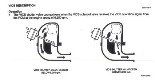
Does anyone have a good same day, A/B dyno of two different stock manifolds? Ideally VICS and squaretop since they only have one runner length to look at? That would be a good way to try and isolate the behavior of the manifolds and validate the graph.
Does anyone have a good same day, A/B dyno of two different stock manifolds? Ideally VICS and squaretop since they only have one runner length to look at? That would be a good way to try and isolate the behavior of the manifolds and validate the graph.
Reply
0
0
01-03-2016, 12:09 PM
#66
Senior Member
Thread Starter
iTrader: (1)
Join Date: Jul 2012
Location: durham NC
Posts: 792
Total Cats: 143
Those are all on boosted engines- which makes them not very useful for trying to determine what wave speed to plug in. Air pressure and temp are big factors, and a boosted engine is going to be working with different parameters for both.
Edit:
Actually the second one looks to be N/A.. Ill see if I can figure out their cam specs.
Edit:
Actually the second one looks to be N/A.. Ill see if I can figure out their cam specs.
Reply
0
0
01-03-2016, 07:46 PM
#67
Senior Member
Thread Starter
iTrader: (1)
Join Date: Jul 2012
Location: durham NC
Posts: 792
Total Cats: 143
Question for someone who knows better. The two sources for math I am using (both are similar) use different methods for effective cam duration. One of them is wrong.
The WPI FSAE paper I am reading shows effective cam duration as
ECD= 720 - duration - 30
Their example is a 288 duration cam and they get a result of ECD 402.
The other example from grapeape racing's PDF file is
ECD = 720 - (Duration - 30)
The example provided is a 305 duration cam with an ECD of 445
Basically, the 30 degree window is being added in one, and subtracted in the other. My question is more, what exactly is effective cam duration? Since it is determined by subtracting the advertised duration from 720 (two crankshaft rotations/one full engine cycle) I am going to assume it is the time between valve events, the time when the valve is closed or near closed.
Links for both source documents:
http://stealth316.com/misc/grapeape-...ionsystems.pdf
https://www.wpi.edu/Pubs/E-project/A...nal_Report.pdf
Edit:
LOL, found another source, this time a book.
https://books.google.com/books?id=KZ...nifold&f=false
They reference the grapeape racing math by name, and steal their example, except they change the ECD math to math WPI's without explanation.
Last edited by asmasm; 01-03-2016 at 08:33 PM.
Reply
0
0

 01-04-2016, 02:33 AM
#69
ʎpunq qoq

Join Date: Jan 2014
Location: Western Australia
Posts: 604
Total Cats: 201
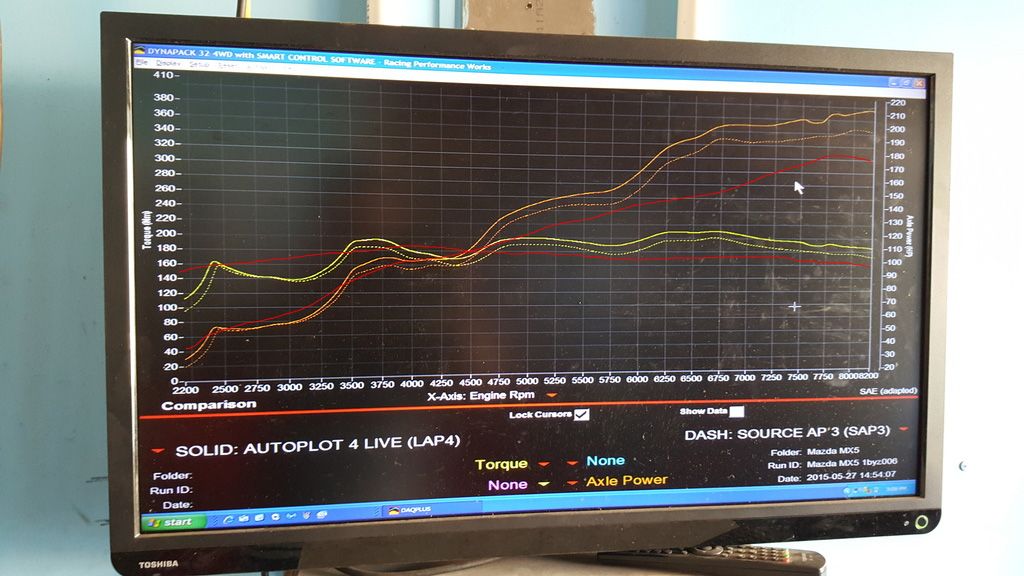
Not sure if it helps you but my dyno shows some very clear harmonic lumps. The manifold is a modified Skunk2 Ultra Street which from memory has a 10inch runner from the bellmouth to the valve. My dyno shows 3 lumps, around 3750, 5000 and 6750 which is pretty close to the spreadsheet data above. The red line is a quick overlay of a stock NA8 manifold.
You can also make custom manifolds by 3D printing your design, test fit and modify to suit then investment cast the final manifold directly from the 3D print. It's great for once off prototyping.... but then it's so much effort to go through when you can just by a Skunk2, hack off the flange and weld a new one on.
You can also make custom manifolds by 3D printing your design, test fit and modify to suit then investment cast the final manifold directly from the 3D print. It's great for once off prototyping.... but then it's so much effort to go through when you can just by a Skunk2, hack off the flange and weld a new one on.
Reply
0
0
01-04-2016, 10:13 AM
#70
Senior Member
Thread Starter
iTrader: (1)
Join Date: Jul 2012
Location: durham NC
Posts: 792
Total Cats: 143
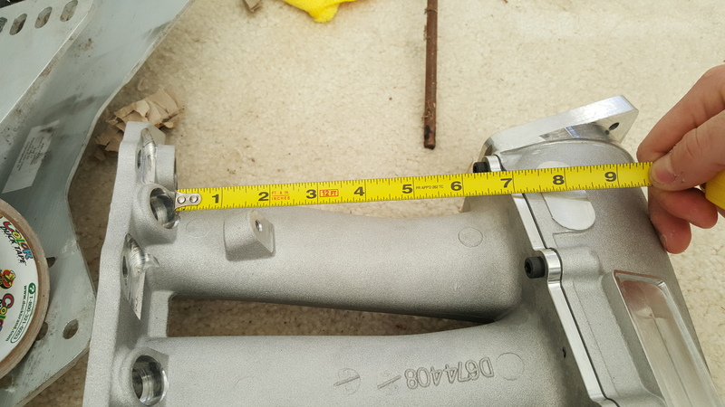
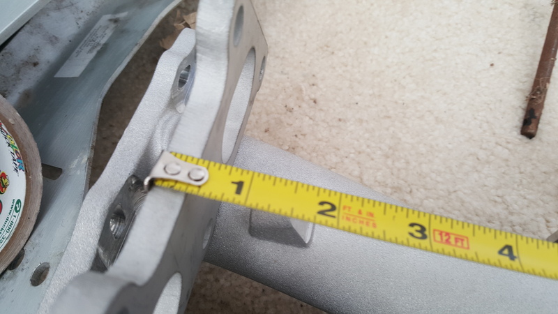
All the numbers on my spreadsheet take into account port depth so the runner lengths are just the lengths of the actual IM runners. I would like to try and do something with a longer runner than the skunk2.
I found your dyno sheet post and tweaked the cam duration for your BP5A cam:

13.558 is the distance to the valve, 8.75 is the runner length on the intake manifold, and those are the third, fourth, fifth, and 6th waves.
The first couple of points match up pretty well. At higher RPM it is off. I have seen other people suggest that this method becomes inaccurate at higher RPMs. I wonder If I can find a scaling factor for RPM that bring things into line.
I found your dyno sheet post and tweaked the cam duration for your BP5A cam:
13.558 is the distance to the valve, 8.75 is the runner length on the intake manifold, and those are the third, fourth, fifth, and 6th waves.
The first couple of points match up pretty well. At higher RPM it is off. I have seen other people suggest that this method becomes inaccurate at higher RPMs. I wonder If I can find a scaling factor for RPM that bring things into line.
Last edited by asmasm; 01-04-2016 at 10:28 AM.
Reply
0
0

 01-04-2016, 12:18 PM
#77
Senior Member
Thread Starter
iTrader: (1)
Join Date: Jul 2012
Location: durham NC
Posts: 792
Total Cats: 143
I found out those FM dyno sheets were using a custom ground intake cam and since it was 8 years ago they don't have the specs around anymore. I am not going to worry about trying to get those to match any math since I don't know what ECD to use.
I also heard back about ECD calculations and the grape ape racing PDF is correct- the WPI PDF is wrong. That means for the 242 advertised duration intake cam on the VVT engines should use an ECD of 508. The BP5A cam in madjack's car should be 499.
I also heard back about ECD calculations and the grape ape racing PDF is correct- the WPI PDF is wrong. That means for the 242 advertised duration intake cam on the VVT engines should use an ECD of 508. The BP5A cam in madjack's car should be 499.
Reply
0
0


