My VVT swap attempt - little different because 1,6 1996 Euro car
#1
Thread Starter
Elite Member
Joined: Mar 2006
Posts: 1,559
Total Cats: 105
From: Schwarzenberg, Germany
Hi guys,
as I received my 2001 VVT engine yesterday I try to prepare myself for a swap into my
1996 1.6 NA - (not known in the US, only in Europe) somewhat different, because it is already wired for sequential injection for instance... (apart from that the wiring doesn't seem to be very different from the 90-93 US 1.6 cars.
I made myself a list of steps to go with the wiring for the swap - according to Savington's writeup.
I would be really happy if one of the experts could check and help me out here and there...
Benefit will be that we will get some more info into the "Connector witch hunt" thread...
1. Starter/Alternator wiring
I am going to use a 1994-1997 1.8 alternator and re-use all the old wiring.
2. Injector / Coolant wiring
I made a little sketch on the wiring on my 1,6 (already sequential fuel) and on the 2001 VVT
Here is the 1.6 wiring (for the Euro 96 car)

Here is the 2001 VVT wiring
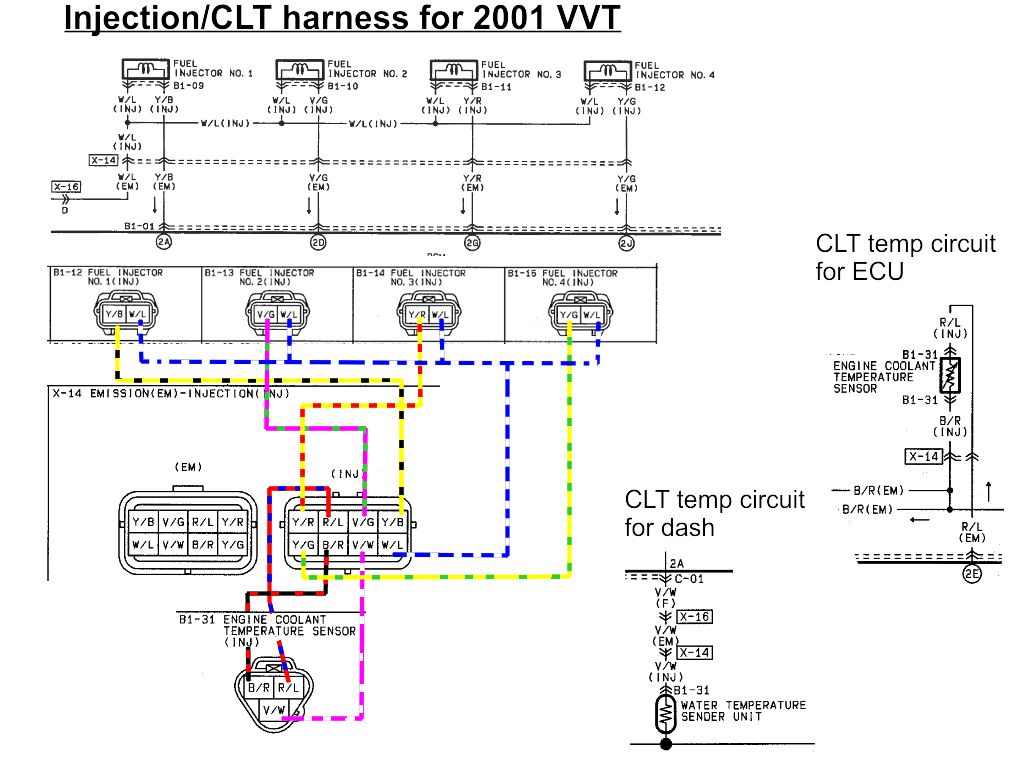
As you can see - they swapped the Inj 1&2 and Inj 3&4 on the 1.6 - God knows why, as the 1.8 wiring is exactly the same as the 2001 VVT...
I think I will de-pin the 1,6 harness and correct the Injector pinout.
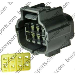
The connector X14 / X12 is the same connector on both cars a
AMP
8 Way Econoseal J Series Mark II
3. CLT
I think I will try to use the 2001 sensor for dash and ECU:
Is checked the resistances of the sensors:
NA
Thermo sensor ECU
20deg C 2.2-2.7kohm
80deg C 0.29-0.35kohm
Temp sensor dash
80 degC 190-260kohm
NBFL 2001
Thermo sensor ECU
20 degC 2.27-2.74kohm
80 degC 0.29-0.34kohm
Temp sensor dash
50 degC 186-204kohm
I think I will use the complete 2001 inj harness for both injectors and also for CLT sensors - should be working out...
4. COIL/IGNITER wiring
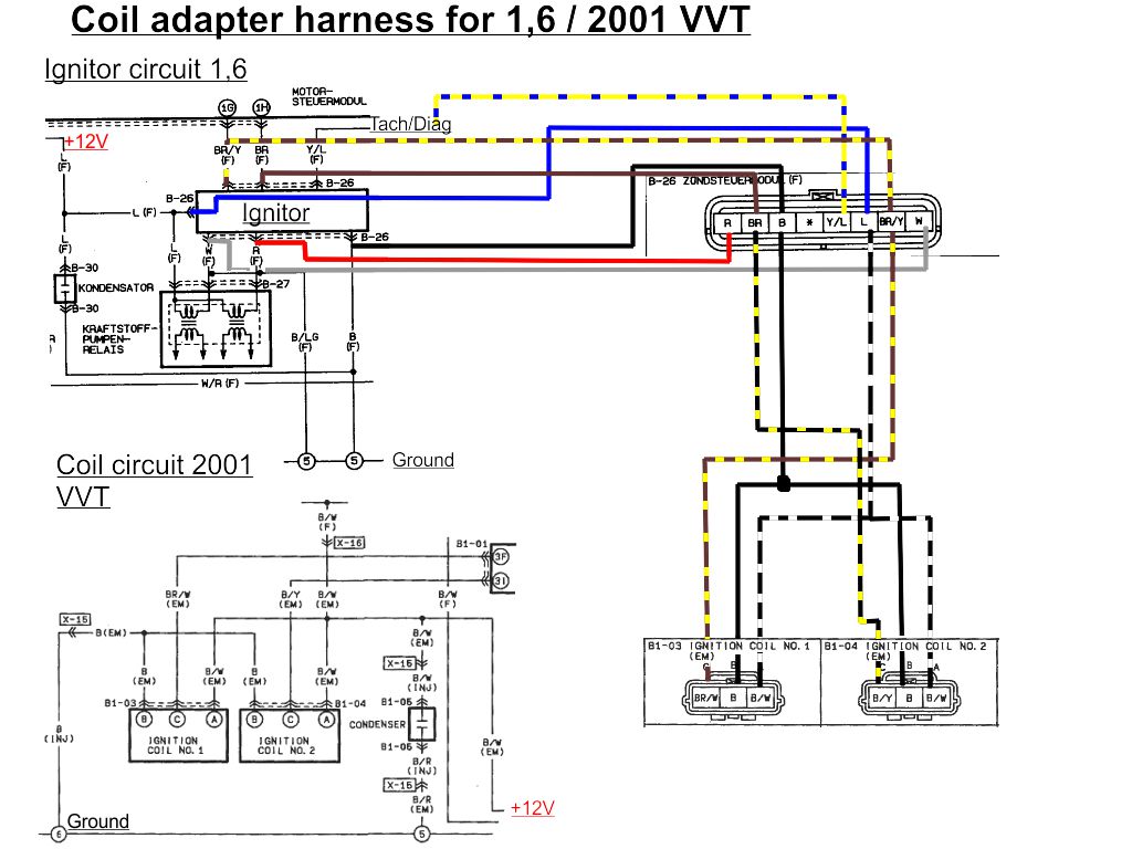
My plan is to make myself an adapter harness between the connector of the igniter and the 2001 coils.
I made a little sketch but I am not sure if this is correct and what needs to be done for the fuelpump...
@Savington - could you eventually help me out here?
5. CAM/CRANK wiring
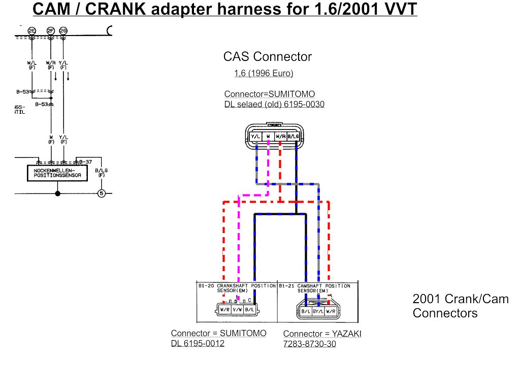
I will also make myself an adapter harness for this
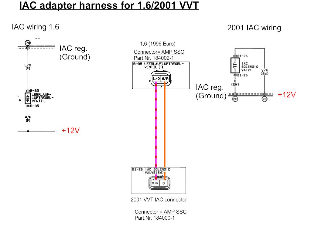
6. IAC wiring
I will also make a little adapter harness for this (I probably just de-pin the 1,6 connector and pin the VVT connector on, as they are of the same system)
1,6 l IAC connector is - AMP SSC Part.Nr. 184002-1
2001 VVT IAC connector is - AMP SSC Part.Nr. 184000-1
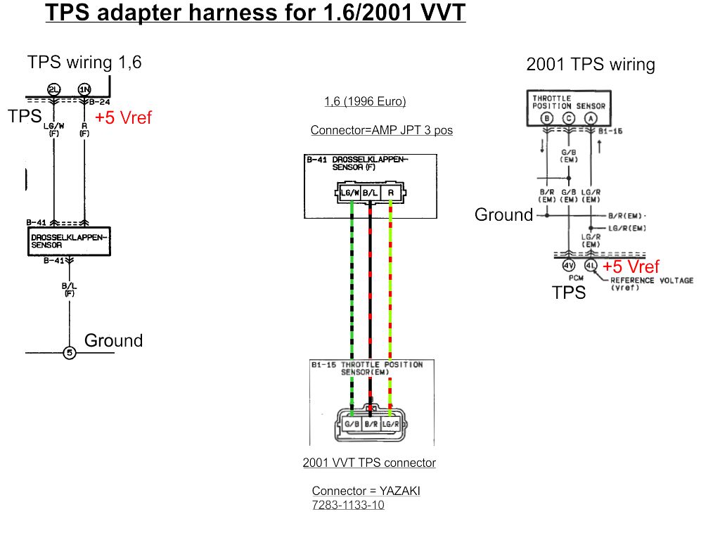
7. TPS wiring
I will also make a little adapter harness for this
1,6 l TPS connector is - Bosch 1237000039 / AMP JPT 3-position
2001 VVT TPS connector is - YAZAKI 7283-1133-10
Here is the sketch for this:
as I received my 2001 VVT engine yesterday I try to prepare myself for a swap into my
1996 1.6 NA - (not known in the US, only in Europe) somewhat different, because it is already wired for sequential injection for instance... (apart from that the wiring doesn't seem to be very different from the 90-93 US 1.6 cars.
I made myself a list of steps to go with the wiring for the swap - according to Savington's writeup.
I would be really happy if one of the experts could check and help me out here and there...
Benefit will be that we will get some more info into the "Connector witch hunt" thread...
1. Starter/Alternator wiring
I am going to use a 1994-1997 1.8 alternator and re-use all the old wiring.
2. Injector / Coolant wiring
I made a little sketch on the wiring on my 1,6 (already sequential fuel) and on the 2001 VVT
Here is the 1.6 wiring (for the Euro 96 car)

Here is the 2001 VVT wiring

As you can see - they swapped the Inj 1&2 and Inj 3&4 on the 1.6 - God knows why, as the 1.8 wiring is exactly the same as the 2001 VVT...
I think I will de-pin the 1,6 harness and correct the Injector pinout.
The connector X14 / X12 is the same connector on both cars a
AMP
8 Way Econoseal J Series Mark II

3. CLT
I think I will try to use the 2001 sensor for dash and ECU:
Is checked the resistances of the sensors:
NA
Thermo sensor ECU
20deg C 2.2-2.7kohm
80deg C 0.29-0.35kohm
Temp sensor dash
80 degC 190-260kohm
NBFL 2001
Thermo sensor ECU
20 degC 2.27-2.74kohm
80 degC 0.29-0.34kohm
Temp sensor dash
50 degC 186-204kohm
I think I will use the complete 2001 inj harness for both injectors and also for CLT sensors - should be working out...
4. COIL/IGNITER wiring
My plan is to make myself an adapter harness between the connector of the igniter and the 2001 coils.
I made a little sketch but I am not sure if this is correct and what needs to be done for the fuelpump...
@Savington - could you eventually help me out here?

5. CAM/CRANK wiring
I will also make myself an adapter harness for this

6. IAC wiring
I will also make a little adapter harness for this (I probably just de-pin the 1,6 connector and pin the VVT connector on, as they are of the same system)
1,6 l IAC connector is - AMP SSC Part.Nr. 184002-1
2001 VVT IAC connector is - AMP SSC Part.Nr. 184000-1

7. TPS wiring
I will also make a little adapter harness for this
1,6 l TPS connector is - Bosch 1237000039 / AMP JPT 3-position
2001 VVT TPS connector is - YAZAKI 7283-1133-10
Here is the sketch for this:

Last edited by Zaphod; 04-15-2013 at 11:32 AM.
#4
From the looks of it, you don't need to touch the injector wiring at all. You'll need to split the CAS into two (which you've already made a note of, it looks right).
The only other things will be small stuff like the rear water neck (keep the 96 one) and running new wires for the IAT and VVT.
The only other things will be small stuff like the rear water neck (keep the 96 one) and running new wires for the IAT and VVT.
#7
Thread Starter
Elite Member
Joined: Mar 2006
Posts: 1,559
Total Cats: 105
From: Schwarzenberg, Germany
a 1996 NA and I will get a 1994-1997 1.8 Alternator... (I change this in Post Nr. 1 - as I will all the changes and additions to keep all in one place)
https://www.miataturbo.net/build-thr...rillian-71861/
#10
Thread Starter
Elite Member
Joined: Mar 2006
Posts: 1,559
Total Cats: 105
From: Schwarzenberg, Germany
- all sensors are in my engine I got
- VVT connector is a Sumitomo SL series 6189-0642 (I got the complete engine harness with my car so I might use the one from the harness - but I would be happy if I could find a source for the Sumitomo and Yazaki connectors over here in Europe)
- CAS connector will be difficult because the connector used is a wire-to-device connector, so there is no mating male connector - I might de-pin it and use another 4pin sealed connector
#11
There's a dickload of pics in the thread now. I'll be labeling them shortly. I still need the VVT connectors/pigtails/harness for the crank sensors, cam sensor, VVT actuator. If you can get these somewhere, awesome.
Coincidentally, I did find the 94 1.8 coil connectors are a direct fit for the CAS connector.
Coincidentally, I did find the 94 1.8 coil connectors are a direct fit for the CAS connector.
#14
Thread Starter
Elite Member
Joined: Mar 2006
Posts: 1,559
Total Cats: 105
From: Schwarzenberg, Germany
Do I get this right from the factory wiring diagramms that the 1.6 NA has all in all 3 coolant sensors? 1 thermo sensor for the ECU (back of the head), 1 temp sensor for the dashboard (also back of the head) and 1 thermo switch for the fan on the front thermostat housing?
I also cross checked the factory manuals for the 1989 NA, the 00 NB and the 2001 NBFL for the sensor resistances and found this
NA
Thermo sensor ECU
20deg C 2.2-2.7kohm
80deg C 0.29-0.35kohm
Temp sensor dash
80 degC 190-260kohm
NB 2000
Thermo sensor ECU
20 degC 2.36-2.53kohm
60 degC 0.56-0.64kohm
Temp sensor dash
50 degC 152-242kohm
NBFL 2001
Thermo sensor ECU
20 degC 2.27-2.74kohm
80 degC 0.29-0.34kohm
Temp sensor dash
50 degC 186-204kohm
So I think one could even reuse the OEM 2001 coolant sensor...
Last edited by Zaphod; 04-15-2013 at 11:07 AM.
#19
Thread Starter
Elite Member
Joined: Mar 2006
Posts: 1,559
Total Cats: 105
From: Schwarzenberg, Germany
Sorry I was unspecific - I will use the Tach out of the MS3(+x), but the wiring to the tach goes from the ignitor to the dash - did the swappers use an extra wire for this or did you jumper wires to get the signal from the MS to the dash?


