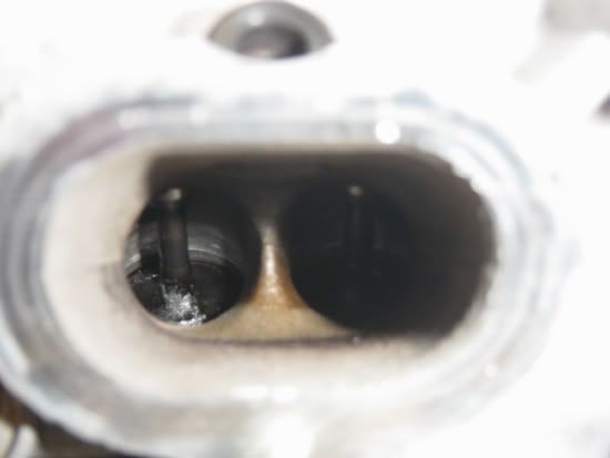
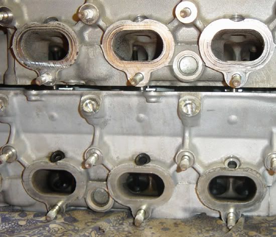
My new 99 head flow numbers with video
#1
So here is the flow numbers on my 99 head.
it has +1mm oversize supertech valves and a port jobb from Racelab.
The black lines are stock ports with stock valves.
The purple line is with a litle bit of porting and stock valves.
The green line is with some putty in the ports to check if in the ports would react to a smaler passage, and stock valves.
The blue line is the final ports with oversized valves port jobb, and reshaped ports.
#4
Maruha had to reduce the base circle diameter to prevent the lobes scraping at just over 9mm of lift. Getting all the way to 10mm of lift will require a completely custom (ie, not off the shelf) cam and some degree of work to get it to fit in the miata head I would expect.
0.6 inches of lift is 15mm of lift, which seems far beyond anything I've ever heard of in miata cams. How much material can you cut away from the head for cam clearance before you hit something important?
Ironically, the green line with the stock valves looks the most interesting to me. It's the kind of thing you could throw into a stock head refresh and see gains from. edit- Assuming there is some sort of welding technique that can substitute the additive effect of the putty.
+1 cats anyway since experiments are always welcome
#8
Whatever they did, it killed your low lift flow. Which is very important on a 4V head. I hope you are running some very high lift cams, because I don't think that headwork will be any better than a stock head with stock cams. You need very high lift to get those ports working the way they are setup now.
EDIT: Green trace looks the best to me, for sure would make the most power on stock cams vs the other traces.
And stock lift on a 99 intake cam is 0.326". What it flows beyond that doesn't matter if the cams aren't going there. What cams are you going to run?
EDIT: Green trace looks the best to me, for sure would make the most power on stock cams vs the other traces.
And stock lift on a 99 intake cam is 0.326". What it flows beyond that doesn't matter if the cams aren't going there. What cams are you going to run?
#9
They have not told me how high the lift will be on the custom cams, but they said they would machine the head to suit the correct camshaft So around .400" to .500" i recon.
In Racelabs flowtest the original 99 head had a flow of:
.400 = 190CFM
And it flowed no more at .500 and .600.
I know it will never run .600 lift but they tested it higher just to see what happend.
here are the final numbers.
.300 = 212CFM
.400 = 252CFM
.500 = 266CFM
.600 = 281CFM
In Racelabs flowtest the original 99 head had a flow of:
.400 = 190CFM
And it flowed no more at .500 and .600.
I know it will never run .600 lift but they tested it higher just to see what happend.
here are the final numbers.
.300 = 212CFM
.400 = 252CFM
.500 = 266CFM
.600 = 281CFM
#10
Whatever they did, it killed your low lift flow. Which is very important on a 4V head. I hope you are running some very high lift cams, because I don't think that headwork will be any better than a stock head with stock cams. You need very high lift to get those ports working the way they are setup now.
EDIT: Green trace looks the best to me, for sure would make the most power on stock cams vs the other traces.
And stock lift on a 99 intake cam is 0.326". What it flows beyond that doesn't matter if the cams aren't going there. What cams are you going to run?
EDIT: Green trace looks the best to me, for sure would make the most power on stock cams vs the other traces.
And stock lift on a 99 intake cam is 0.326". What it flows beyond that doesn't matter if the cams aren't going there. What cams are you going to run?

The air velocity is increased at the lower lift .100-.200" at .100 overlap occurs, and the flowpotencial is lowered compared to the OEM ports, we dont want any reversation of exhaust gasses, and we want to maintain high air velocity. The tought is that a high flowing port also flows very well backwards, and to empty the combustion chamber into the intake ports and manifold is not something we want... The exhaust ports will be set up to flow a lot at low valvelift.
Since this engine will also be a turboengine later on, the backpressure will also have to be taken into consideration.
The camshaft will have a agressive opening ramp to match the ports.
#11
Just out of curiosity, how much does this whole treatment cost?
Will there be any problems from running a super steep high lift profile? Stock cam lobes have a lot of room to play around with in terms of lifter surface area but beyond a certain point, aren't you going to be peeking over the edge and putting lateral forces on the lifter/valve as the cam turns?
Will there be problems past a certain point with reducing the base circle? You can't realistically lower the cam journals in the head, which means that your lifters are going to have to poke further up to meet them. And since you're already removing head material from around the lifters to make room for the big lobes, is this going to be a durability issue?
I do find it kind of interesting how the stock/head valve setup doesn't seem to benefit from extra lift past .4" lift, but seems to pick up a lot of gains between .2" and .3". I could definitely see an argument for a drop in replacement cam that uses a slightly reduced base circle to run 10mm max lift and a quicker opening on an otherwise stock duration. Would this require SUB? Would an extra .1" of lift turn the BP into an interference engine?
#12
If you reduce the base circle on a stock cam you will not have problems with interference with the head where you would with keeping the factory 36mm base circle and increasing cam lift. The danger of cutting factory cams lies in the potential to remove the outer hardening that most (not sure about Mazda) manufactures put on their cams. In theory you can grind a factory cam to 10mm lift or more very easily.
8.28mm intake - 1.72 off the base gives you 10mm
8.89mm exhaust -1.11 off the base gives you 10mm
Cutting the base down to the 33mm Mahura base circle gets you to an easy 11mm lift
Now that being said, it's not that simple to remove material from the base circle of a camshaft without considering the ramp and acceleration. This can go on but it's not a cam discussion thread, if anyone would like to have a more in depth discussion I would be interested in joining in.
If you don't break a timing belt the only time you have to worry about the engine being "interference" is during valve adjustments. This should be addressed when building the engine. Valve to valve clearance also becomes an issue especially for the VVT engines.
I currently have a set of VVT cams at my grinder seeing what is possible on the factory cams by reducing the base circle ~1mm. I'll share what I can.
#19
So i finaly got the head milled to make rom in the head for the new cams.
I ended up with 12,5 mm lift on the intake cam and 12mm lift on the exhaust cam.
And i just got my hands on a 1995cc Flyin miata 9:1 stroker kit. so i am thrilled to see how this will work out.
the engine should be in the car next summer and run a year as a NA engine before i build the turbo kit.
I ended up with 12,5 mm lift on the intake cam and 12mm lift on the exhaust cam.
And i just got my hands on a 1995cc Flyin miata 9:1 stroker kit. so i am thrilled to see how this will work out.
the engine should be in the car next summer and run a year as a NA engine before i build the turbo kit.


