

Miata LFX Swap (Singular Motorsports & Good-Win Racing)

 05-01-2016, 02:20 PM
#222
Supporting Vendor

Thread Starter
iTrader: (3)

Join Date: Jul 2006
Location: San Diego
Posts: 3,304
Total Cats: 1,225
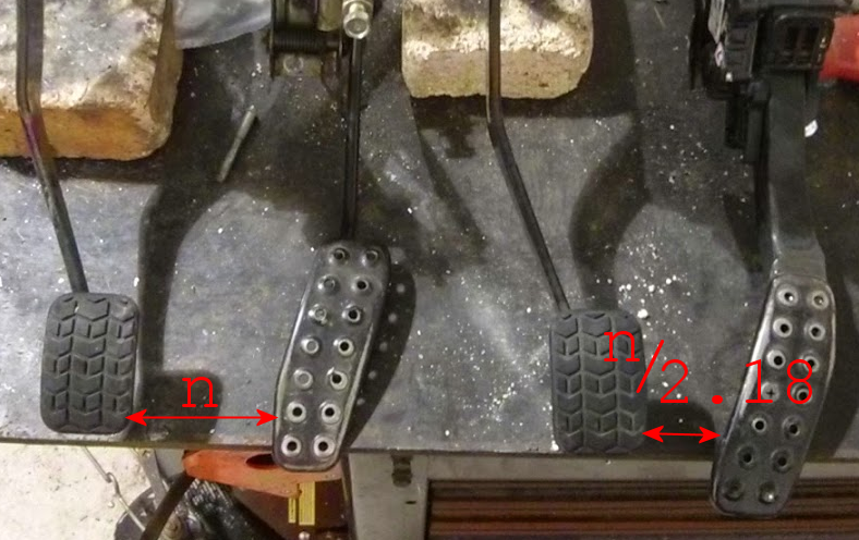
Yeah I saw in your build thread that you changed that shortly after. Mine is centered on the factory pedal's original position (Camaro pedal is slightly narrower)


Reply
 0
0

0
05-02-2016, 12:06 AM
#223
Supporting Vendor
Thread Starter
iTrader: (3)
Join Date: Jul 2006
Location: San Diego
Posts: 3,304
Total Cats: 1,225
"Cutting corners" in the engine bay to clear the LFX
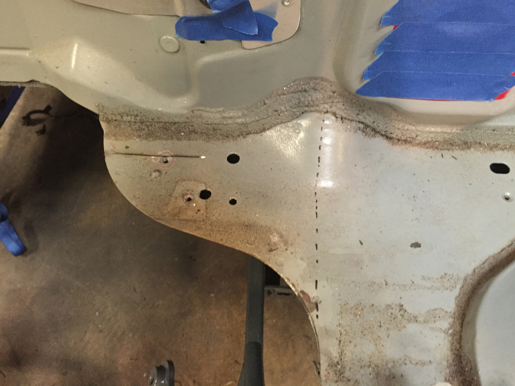
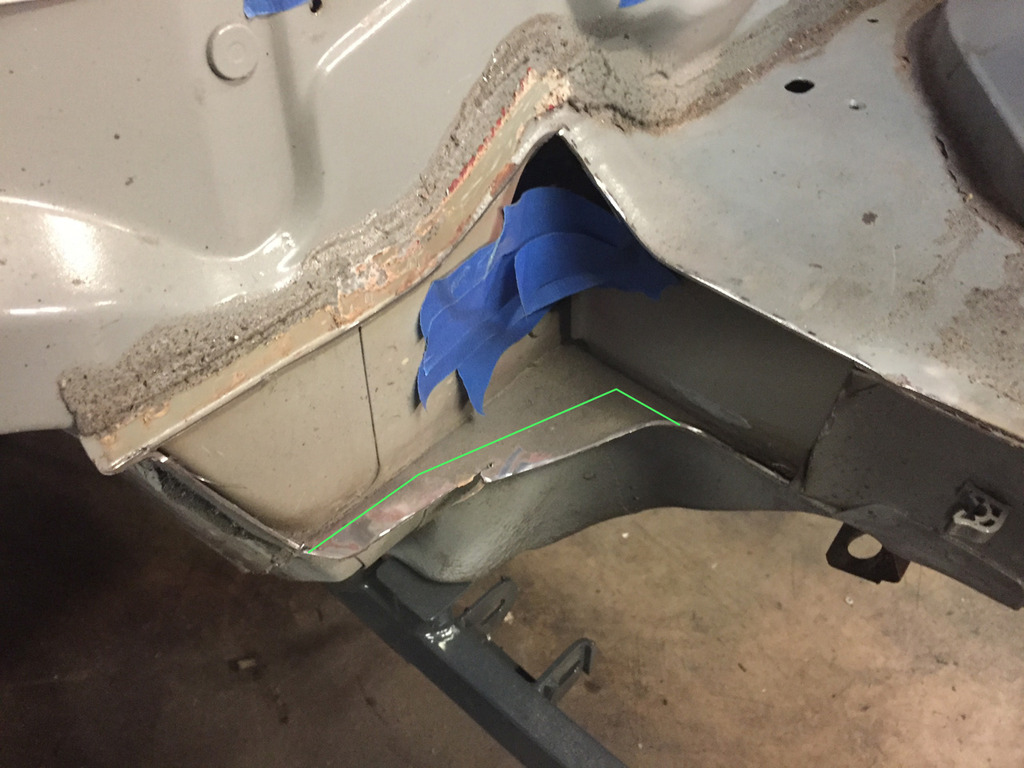
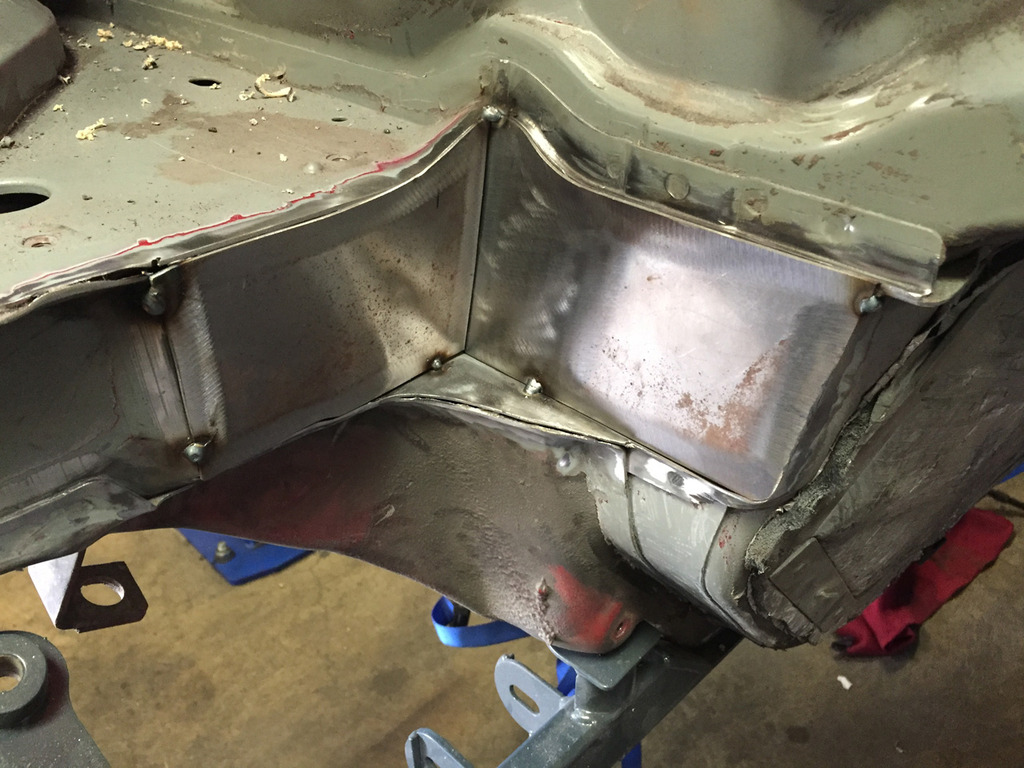
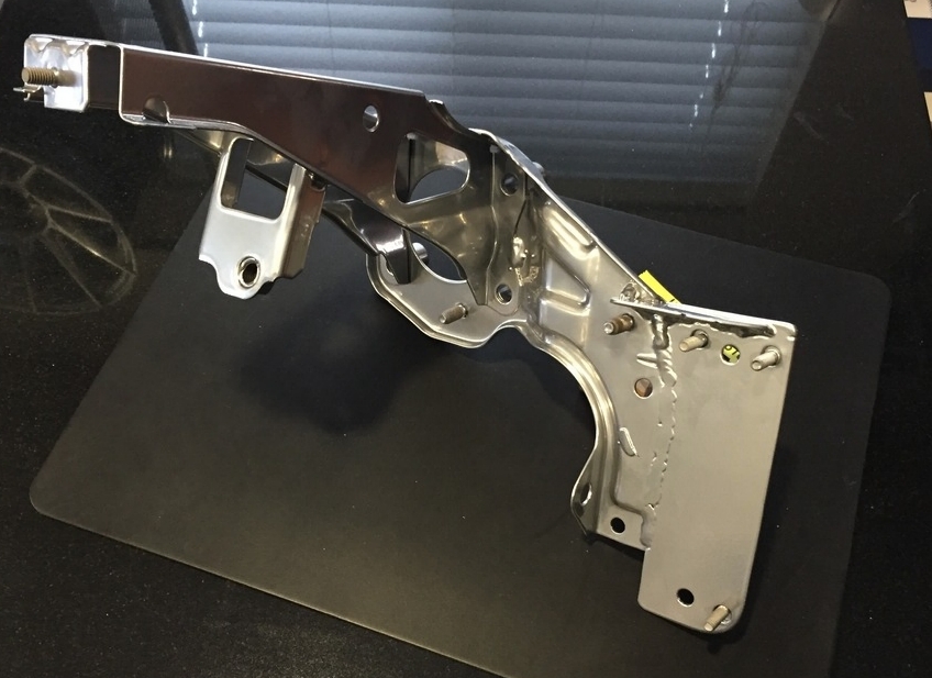
Got tired of cleaning goo out of seams so today I tackled the engine bay mod necessary to fit the LFX. V8 swaps do this same mod to the rear corners, but they also require heavy changes to the transmission tunnel/firewall. For the LFX, you only need to cut the rear corners of the bay. (yay!)
These are the offending corners, dotted line shows where they need to be squared off:
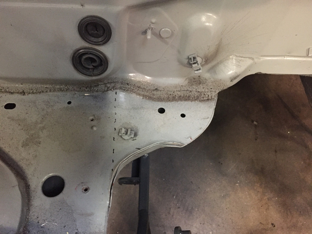
First cuts were tentative, just to see what we're dealing with behind there. The steering column passes through this area on the driver's side so that had to be removed of course:
[IMGhttp://i175.photobucket.com/albums/w157/ThePass_photos/The%20Miata/2015%20LFX%20Swap/Engine%20Bay%20Mods/DR%20side%20bay%20cut%202_zpsm482rpam.jpg[/IMG]
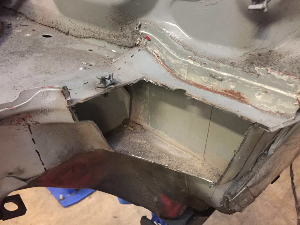
After more cutting. The below pics are almost there, but still more to take off the lower shelf. That shelf meets with a layer of sheet metal that comes up from below, so you don't want to take it out entirely. You want to remove as much as possible without removing that sandwich - basically cut until you see the layers separating and then weld them back together. I've added the green lines to show approximately how much is left once you've cut it back enough:
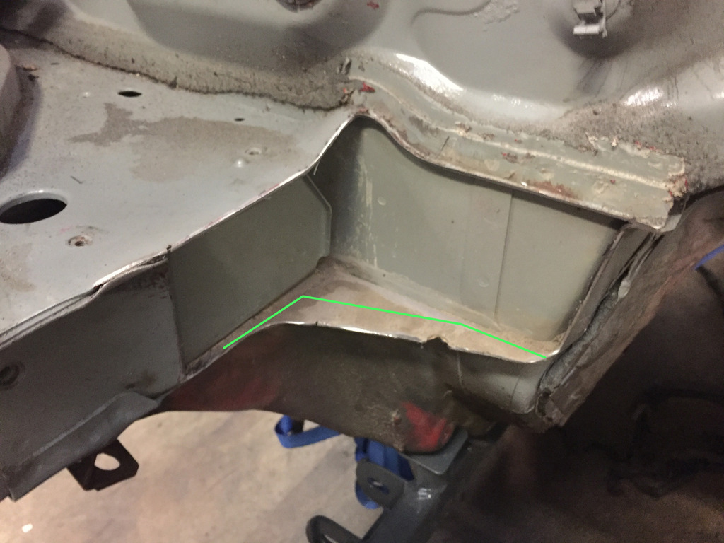
I did some searching around for what others have done to weld up this area and bring strength back to compensate for what was removed, and frankly I haven't liked anything I saw. A lot of methods, including what FM does in-house for V8 stuff is just a small bit of angled steel welded into the corner, with the rest of the exposed sheet metal edges just welded to whatever is nearby.
IMO, the full area where material was cut out should have plates welded in to transfer loads, as well as seal that area up as much as possible.
So, the plates:
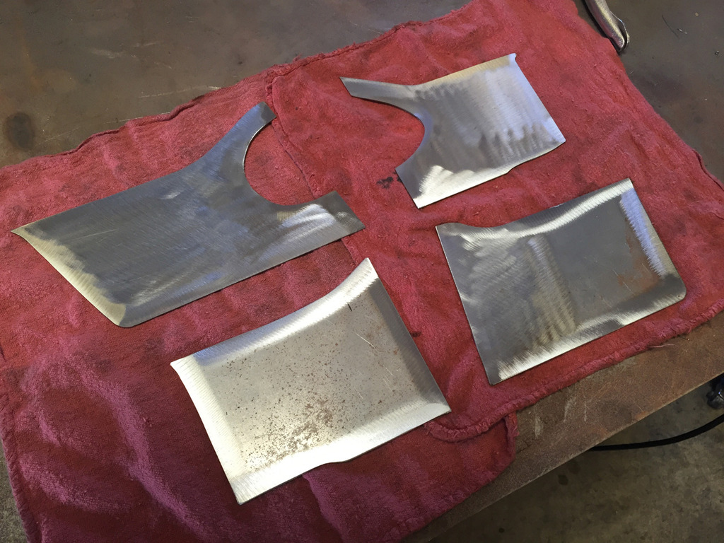
Tacked into place, you can see how they tie each "loose end" where something was cut away back together:
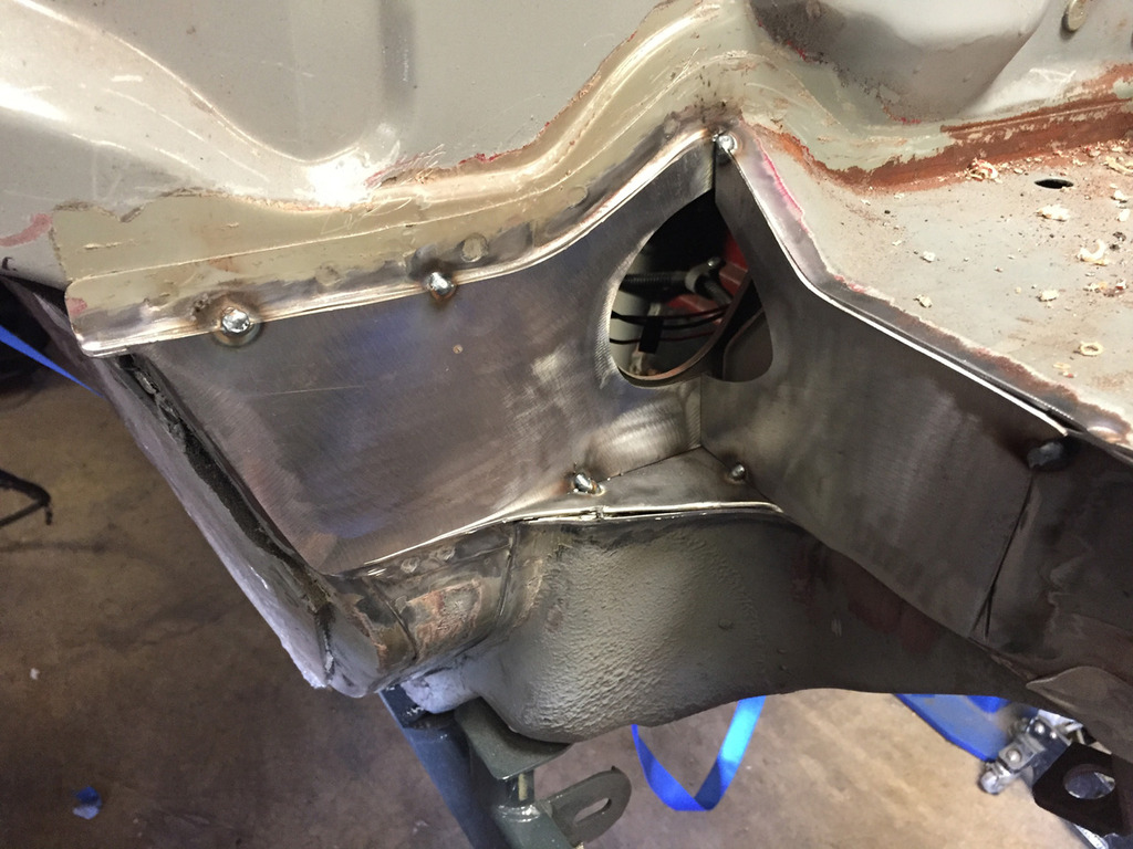
After much welding...
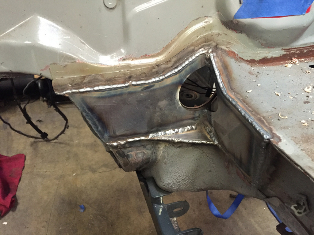
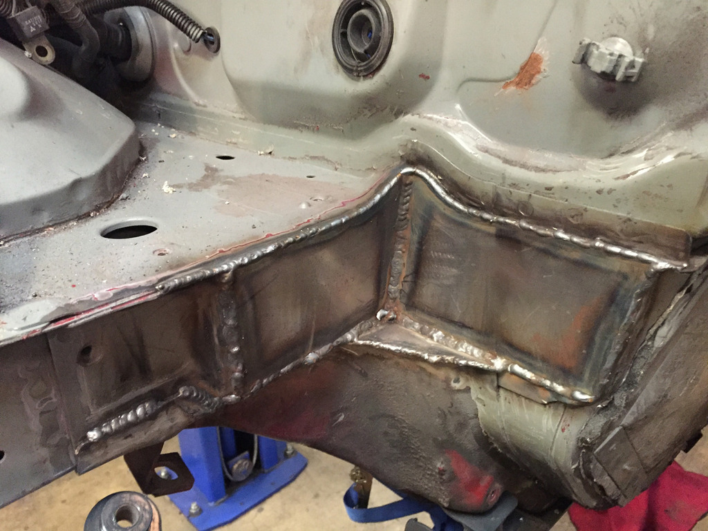
Pay no mind to the un-stitched seams nearby, that's coming next.
Got tired of cleaning goo out of seams so today I tackled the engine bay mod necessary to fit the LFX. V8 swaps do this same mod to the rear corners, but they also require heavy changes to the transmission tunnel/firewall. For the LFX, you only need to cut the rear corners of the bay. (yay!)
These are the offending corners, dotted line shows where they need to be squared off:
First cuts were tentative, just to see what we're dealing with behind there. The steering column passes through this area on the driver's side so that had to be removed of course:
[IMGhttp://i175.photobucket.com/albums/w157/ThePass_photos/The%20Miata/2015%20LFX%20Swap/Engine%20Bay%20Mods/DR%20side%20bay%20cut%202_zpsm482rpam.jpg[/IMG]
After more cutting. The below pics are almost there, but still more to take off the lower shelf. That shelf meets with a layer of sheet metal that comes up from below, so you don't want to take it out entirely. You want to remove as much as possible without removing that sandwich - basically cut until you see the layers separating and then weld them back together. I've added the green lines to show approximately how much is left once you've cut it back enough:
I did some searching around for what others have done to weld up this area and bring strength back to compensate for what was removed, and frankly I haven't liked anything I saw. A lot of methods, including what FM does in-house for V8 stuff is just a small bit of angled steel welded into the corner, with the rest of the exposed sheet metal edges just welded to whatever is nearby.
IMO, the full area where material was cut out should have plates welded in to transfer loads, as well as seal that area up as much as possible.
So, the plates:
Tacked into place, you can see how they tie each "loose end" where something was cut away back together:
After much welding...
Pay no mind to the un-stitched seams nearby, that's coming next.
Reply
6
6
05-02-2016, 05:13 PM
#226
Supporting Vendor
Thread Starter
iTrader: (3)
Join Date: Jul 2006
Location: San Diego
Posts: 3,304
Total Cats: 1,225
Thank you sir.
Can't wait. There is much conflict between wanting to get it done right meow so that I can get to enjoying it and adding more to the work load by taking the time to do other things while I'm in here.
Can't wait. There is much conflict between wanting to get it done right meow so that I can get to enjoying it and adding more to the work load by taking the time to do other things while I'm in here.
Reply
0
0
 05-04-2016, 12:08 AM
#229
Supporting Vendor
Thread Starter
iTrader: (3)
Join Date: Jul 2006
Location: San Diego
Posts: 3,304
Total Cats: 1,225
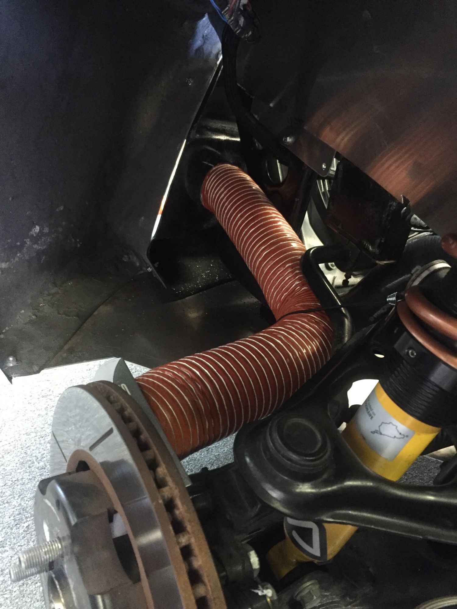
Differential temperature sensor
Tonight I turned attention back to the differential. With a seized axle in the first diff I purchased, I bought another 3.42 limited slip Getrag. This one arrived with both axles already removed (a good sign!).
Just like the transmission, I want to have solid data on what temperatures the differential is seeing under hard use so that I can determine whether or not coolers will be needed. So, my first step is to add a temperature sensor. I'm again using an Accutech SMI oil temp gauge for this as they are super accurate and affordable.
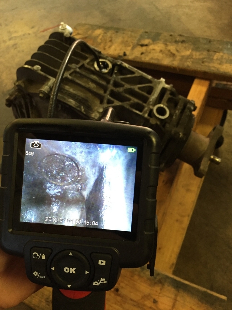
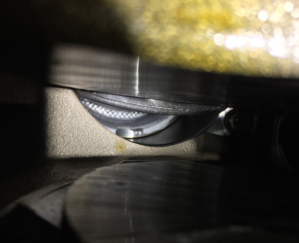
Drained the diff and then flipped it over and scoped the inside through the drain hole. Turns out there's a perfect spot for the sensor. In this first pic you can see just looking in from the drain hole at the right side of the diff that there's a partition just ahead of the drain hole but then a nice flat area on the inside wall just behind that:
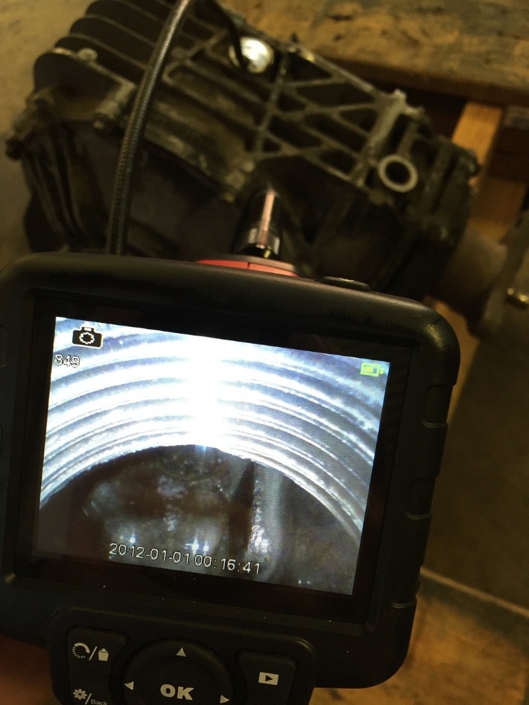
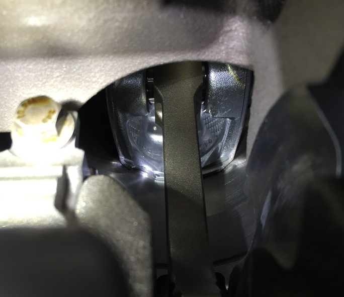
Moving further in, we get a good look at that flat area and you can see there is a circle cast into the inside wall there:
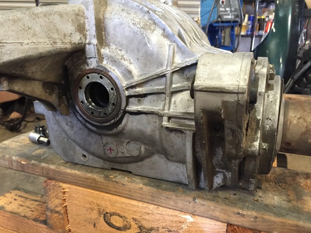
Interestingly, that inner circle corresponds to one of two circles in the outside casting. Red "X" marks the spot for drilling on the rear circle. DON'T mix them up and drill into the forward circle as that will put you right into the partition on the inside:
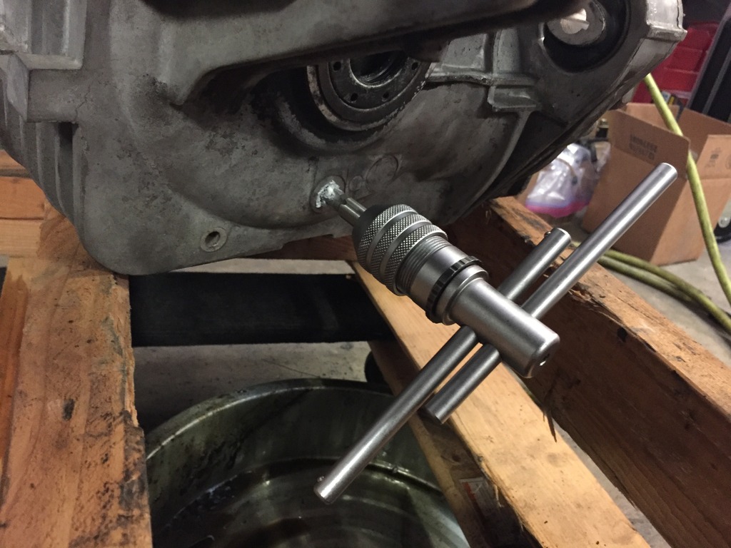
Once again, drill a pilot then drill out with "O" size bit using grease on the bit to catch shavings. Then tap for 1/8-27 NPT threads. Do this with the diff right-side-up so that any shavings that do end up inside fall towards the drain:
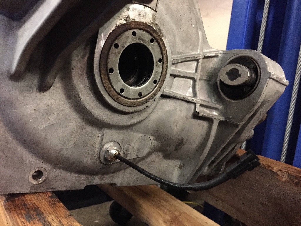
Sensor installed (and after cleaning up the diff housing):
Tonight I turned attention back to the differential. With a seized axle in the first diff I purchased, I bought another 3.42 limited slip Getrag. This one arrived with both axles already removed (a good sign!).
Just like the transmission, I want to have solid data on what temperatures the differential is seeing under hard use so that I can determine whether or not coolers will be needed. So, my first step is to add a temperature sensor. I'm again using an Accutech SMI oil temp gauge for this as they are super accurate and affordable.
Drained the diff and then flipped it over and scoped the inside through the drain hole. Turns out there's a perfect spot for the sensor. In this first pic you can see just looking in from the drain hole at the right side of the diff that there's a partition just ahead of the drain hole but then a nice flat area on the inside wall just behind that:
Moving further in, we get a good look at that flat area and you can see there is a circle cast into the inside wall there:
Interestingly, that inner circle corresponds to one of two circles in the outside casting. Red "X" marks the spot for drilling on the rear circle. DON'T mix them up and drill into the forward circle as that will put you right into the partition on the inside:
Once again, drill a pilot then drill out with "O" size bit using grease on the bit to catch shavings. Then tap for 1/8-27 NPT threads. Do this with the diff right-side-up so that any shavings that do end up inside fall towards the drain:
Sensor installed (and after cleaning up the diff housing):
Reply
2
2
 05-04-2016, 05:39 AM
#231
Elite Member

Join Date: Sep 2015
Location: Seattle, WA
Posts: 1,651
Total Cats: 885
Differential temperature sensor
Tonight I turned attention back to the differential. With a seized axle in the first diff I purchased, I bought another 3.42 limited slip Getrag. This one arrived with both axles already removed (a good sign!).
Just like the transmission, I want to have solid data on what temperatures the differential is seeing under hard use so that I can determine whether or not coolers will be needed. So, my first step is to add a temperature sensor. I'm again using an Accutech SMI oil temp gauge for this as they are super accurate and affordable.
Drained the diff and then flipped it over and scoped the inside through the drain hole. Turns out there's a perfect spot for the sensor. In this first pic you can see just looking in from the drain hole at the right side of the diff that there's a partition just ahead of the drain hole but then a nice flat area on the inside wall just behind that:
Moving further in, we get a good look at that flat area and you can see there is a circle cast into the inside wall there:
Interestingly, that inner circle corresponds to one of two circles in the outside casting. Red "X" marks the spot for drilling on the rear circle. DON'T mix them up and drill into the forward circle as that will put you right into the partition on the inside:
Once again, drill a pilot then drill out with "O" size bit using grease on the bit to catch shavings. Then tap for 1/8-27 NPT threads. Do this with the diff right-side-up so that any shavings that do end up inside fall towards the drain:
Sensor installed (and after cleaning up the diff housing):
Reply
0
0
 05-07-2016, 02:57 PM
#235
Boost Pope

iTrader: (8)
Join Date: Sep 2005
Location: Chicago. (The less-murder part.)
Posts: 33,482
Total Cats: 6,898
True story:
I never realized that part of the car was removable.
Also, the addition of a 3 minute poached egg to a hamburger (along with the usual sliced, pickled jalapenos, a dab of catchup, and some sriracha) is quite nice.
Reply
0
0

 05-08-2016, 03:36 AM
#238
Supporting Vendor
Thread Starter
iTrader: (3)
Join Date: Jul 2006
Location: San Diego
Posts: 3,304
Total Cats: 1,225
Got into the motor today, starting to get familiar with it.
Oil pan pulled to swap it for the low-profile one courtesy of V8R. Have to pull the crank pulley to pull the pan, and I had to take a grinder to one of our pulley pullers to narrow the fingers so the would fit the pulley. Also ordered a new crank pulley bolt as it is torque-to-yield, part number 11569873:
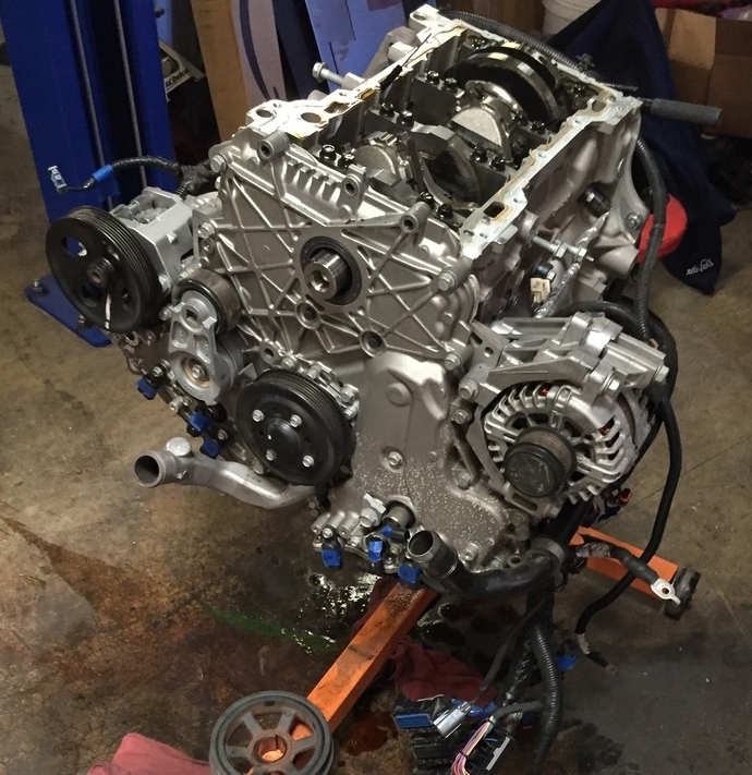
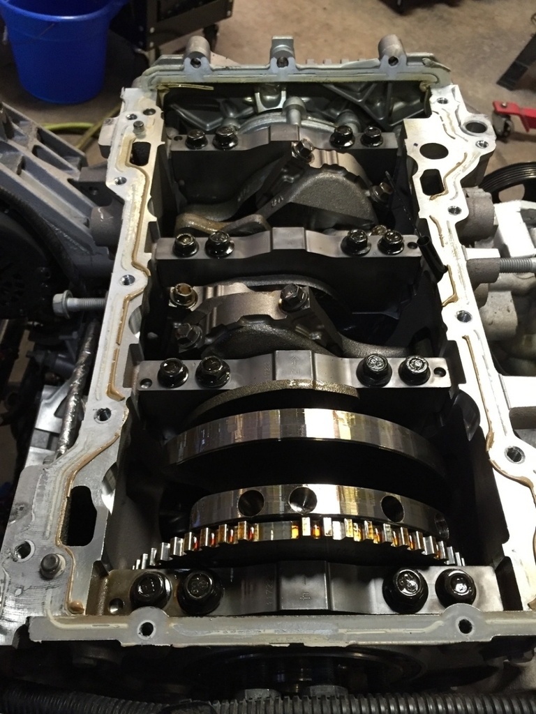
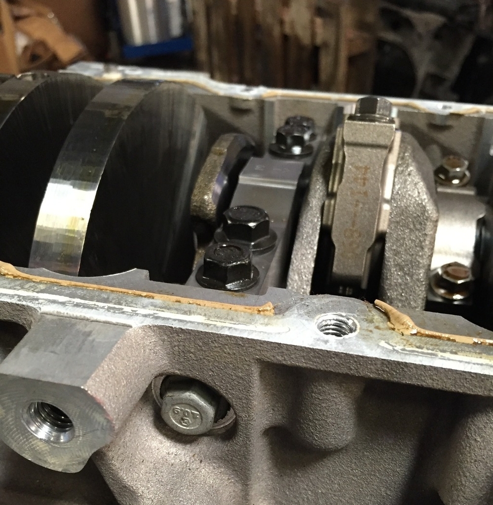
Crank trigger wheel is internal and located at the back of the engine. Beefy 6-bolt main bearing caps (4 from the bottom and 1 of each side coming through the block wall). View in this pic is from the back of the motor:
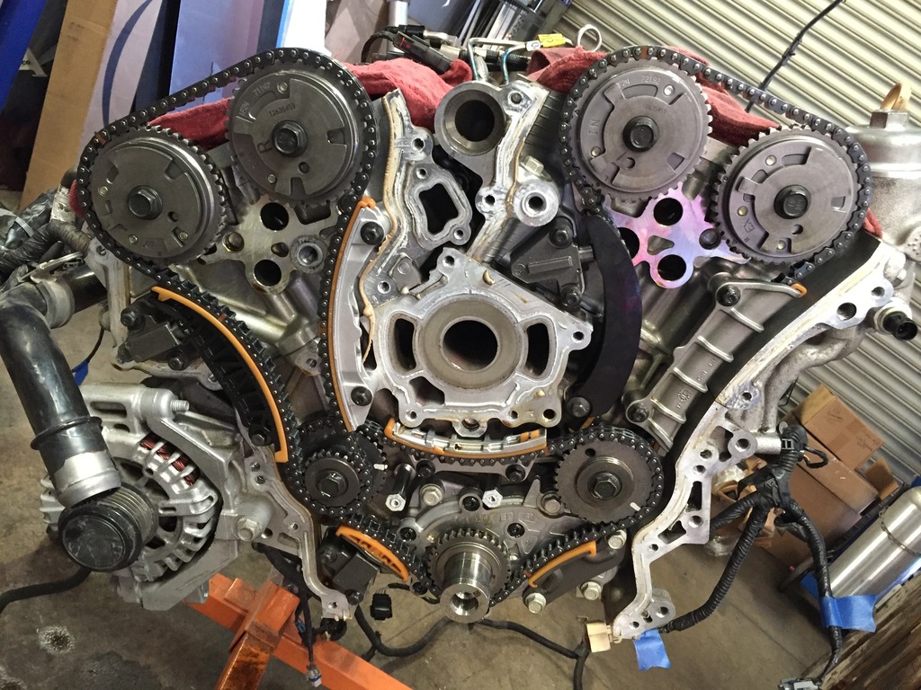
My particular engine came from a Camaro that had flipped in an accident (it wanted to be a Mustang). This meant some extra work for me because the oil cap had been broken (part number 12642516) and some dirt had made its way into the driver's side valve cover/cam area and that meant more disassembly to clean everything out. Not wanting to risk missing anything, I pulled both the valve covers and the main front cover so I could thoroughly clean everything. To pull the front engine cover you need to remove the power steering pump, and to remove that you need to first remove the pulley on that pump. While I was in there, I also found that one of the four cam position sensors was cracked, so a replacement for that is also on order (part number CSS1909). There are 3 timing chains:
Oil pan pulled to swap it for the low-profile one courtesy of V8R. Have to pull the crank pulley to pull the pan, and I had to take a grinder to one of our pulley pullers to narrow the fingers so the would fit the pulley. Also ordered a new crank pulley bolt as it is torque-to-yield, part number 11569873:
Crank trigger wheel is internal and located at the back of the engine. Beefy 6-bolt main bearing caps (4 from the bottom and 1 of each side coming through the block wall). View in this pic is from the back of the motor:
My particular engine came from a Camaro that had flipped in an accident (it wanted to be a Mustang). This meant some extra work for me because the oil cap had been broken (part number 12642516) and some dirt had made its way into the driver's side valve cover/cam area and that meant more disassembly to clean everything out. Not wanting to risk missing anything, I pulled both the valve covers and the main front cover so I could thoroughly clean everything. To pull the front engine cover you need to remove the power steering pump, and to remove that you need to first remove the pulley on that pump. While I was in there, I also found that one of the four cam position sensors was cracked, so a replacement for that is also on order (part number CSS1909). There are 3 timing chains:
Last edited by ThePass; 05-08-2016 at 06:09 PM.
Reply
0
0
 05-08-2016, 04:11 AM
#240
Supporting Vendor
Thread Starter
iTrader: (3)
Join Date: Jul 2006
Location: San Diego
Posts: 3,304
Total Cats: 1,225
Not that bad of a job as long as you've got some time and a puller/pusher that works on that P/S pulley. Silicone scraping and re-applying on that massive front engine cover is a little tedious though 
Some sockets that usually lie in the toolbox untouched in a Miata shop are getting some action on this new motor... 1/2", 15mm , 18mm, 22mm
Yeah the cross-hatch on the bottom of the pistons looks pretty standard. Will take a couple pics of the counterweights tomorrow.
Some sockets that usually lie in the toolbox untouched in a Miata shop are getting some action on this new motor... 1/2", 15mm , 18mm, 22mm
Yeah the cross-hatch on the bottom of the pistons looks pretty standard. Will take a couple pics of the counterweights tomorrow.
Reply
0
0


