

Few engine refreshing tips needed
 01-21-2010, 07:34 AM
#41

+1
I started on my head last night after getting all the valves out...and could use pointers.
I know to hit all the points that Braineack and the Hakuna guy (Larry?) talk about...but am unsure as to how much material I can take out of the runners.
Right now I'm just bowl-blending and removing casting ridges.

Reply
 0
0

0
01-21-2010, 08:12 AM
#42
Junior Member
Thread Starter
iTrader: (1)

Join Date: Apr 2008
Location: Bristol
Posts: 439
Total Cats: 0
I'm not entirely sure how good my port job would be for a turbo charged application. I removed a lot of material from the top of the runners in order to straighten the run into the cylinder ( if pat were still here he would no doubt disapprove). If I could I would probably weld some material back on the bottom to regain some port velocity. I also re-shaped the web between the two valve "runners" at the bottom of the port. ATM I'm busy making a tool to cut the valve seat throat wider to accomodate the larger valves before I cut new angles on the seat. It's basically going to be an end mill ground with a small chamfer ground on the tips mounted on a mandrel the same diameter as a valve stem.
Reply
0
0
01-21-2010, 08:26 AM
#44
Junior Member
Thread Starter
iTrader: (1)
Join Date: Apr 2008
Location: Bristol
Posts: 439
Total Cats: 0
Measuring is your freind. With the thermostat housing removed you can see the "back" of the ports in the water jacket. Use large calipers (big bow legged things not a vernier) and you can see how much material you have to play with in the bowls. Most of the material that has to be removed to straighten comes from the bit that protrudes from the main casting so no danger there. I was fortunate enough to have access to ultrasonic NDT equipment at work to measure the depth of the water jacket in other places.
Reply
0
0
01-21-2010, 11:46 AM
#45

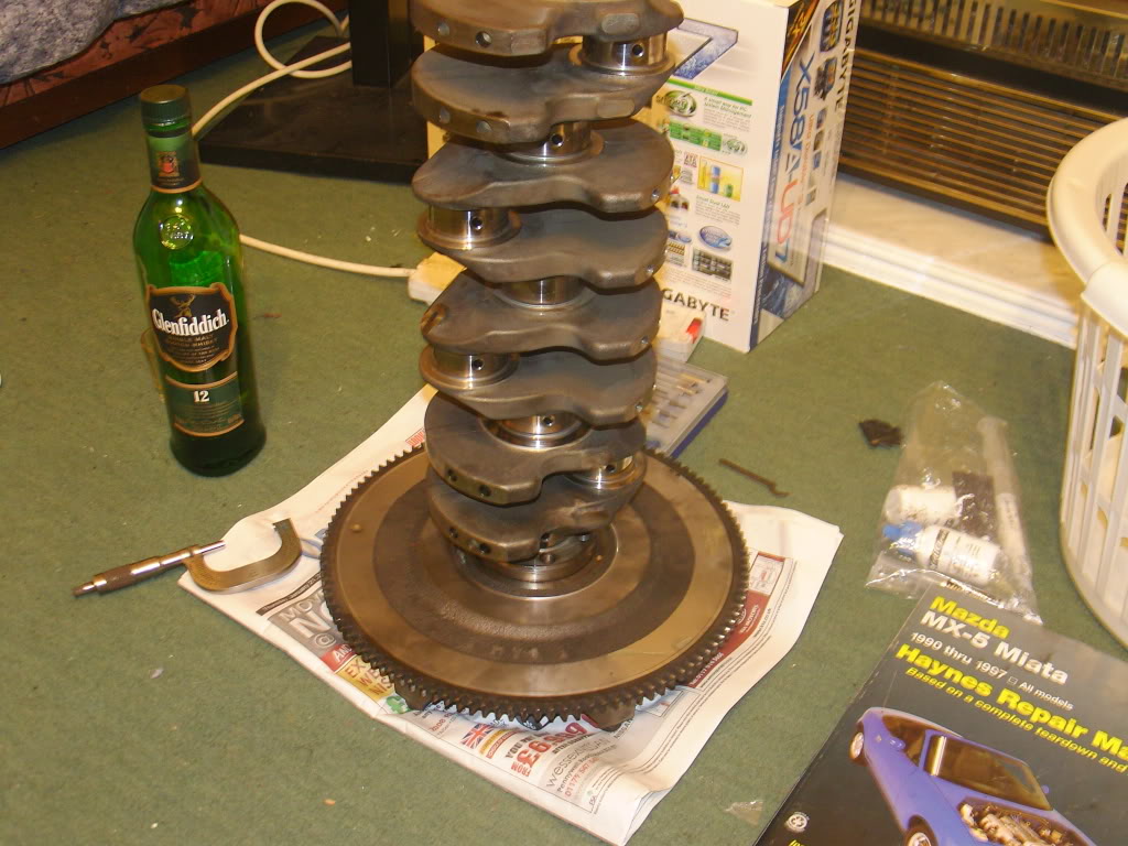
Ok next series of questions. I have pulled the crank now and gone over it with the micrometer. Endfloat and main bearings are perfect at just above mid limit and the surface looks good. The rod jornals have a nice surface on them but are close to bottom limit. The rod shells show the expected polishing at the top and bottom. Can I assume that this is all ok to go ahead with seeing as it's all within haynes manual tolerances?
Also my oil seals seem to have worn slight polished grooves in their "journals" front and back and the haynes manual seems to get a bit enthusiastic over this saying that the crank should be ground and a sleeve pressed on! This seems extreme, I mean it wasn't actually leaking before I tore the motor down. Any opinions? I'm going with "if it ain't broke don't fix it" for now until Im told otherwise.
Tia
On the crank, I'd have the rod/main journals polished and leave it alone. As for the seal areas, sometimes you can press the seal in a little less (or further) to get the lip out of that groove. There are also "seal saver" pieces which look like a super thin tube with a flange that's been scored. You drive the tube on and then crack off the pre-scored flange leaving you a new seal area. We used these pretty commonly on old Brit engines, since after 40 or 50 years the seal areas get some pretty large grooves... and they weren't known for sealing well when new. No idea where you'd get them in the UK however. Here's an example of what I'm talking about... not our application but you get the idea. Amazon.com: National Seal 99372 Crankshaft Oil Seal: Automotive
Reply
0
0
01-22-2010, 03:37 PM
#46
Junior Member
Thread Starter
iTrader: (1)
Join Date: Apr 2008
Location: Bristol
Posts: 439
Total Cats: 0
Thanks for the info Renn, I haven't seen those before despite working on quite a few old brit engines myself. The way we always looked at it was "its designed to leak as a form of corrosion protection" I have never yet found an MG with a rusty sump 
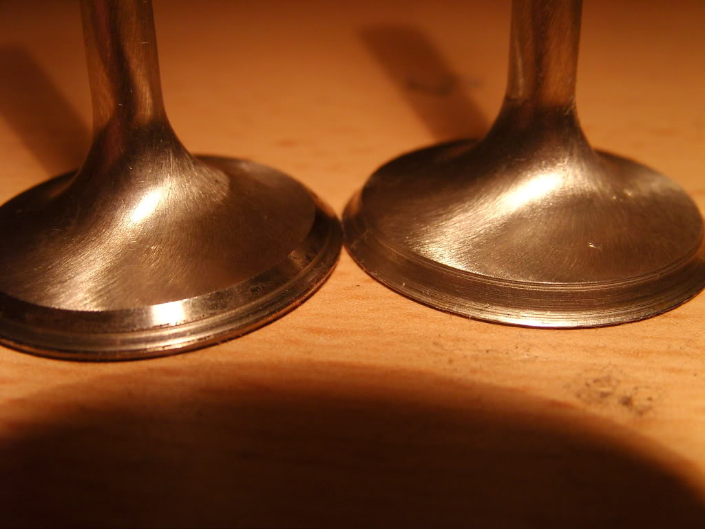
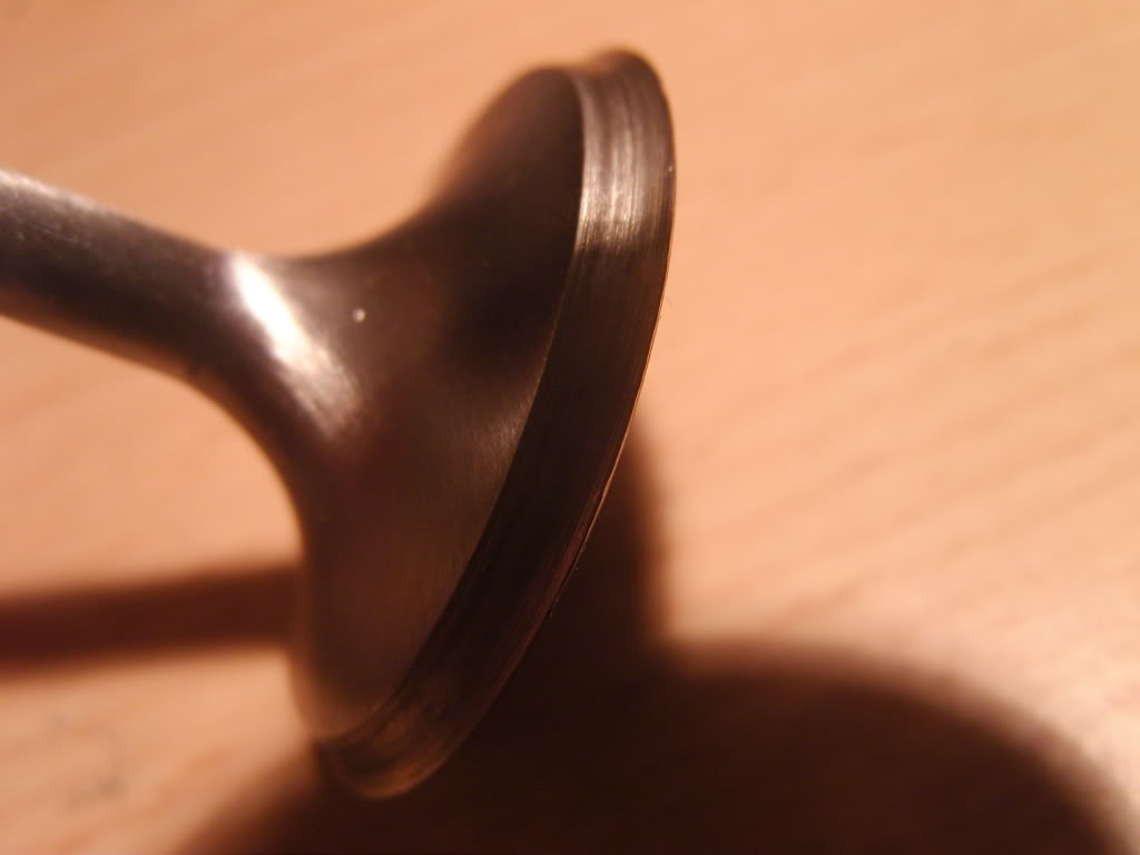
In other news unfortunately I won't be getting +1mm valves atm. I bought some second hand from pschmidt that he pulled from a spare head but unfortunately despite his machinists assurances, they're toast. He has been very kind and refunded the total amount despite me telling him to keep the shipping costs (thank you very much Patrick).
The reason I bring this to peoples attention is they are toast in a very abnormal way and I really want to know what happened to them. The exhaust valves look reasonable, there is no shiny seat margin on them but they look like they might lap in or at a push need grinding. But the inlet valves are frazzled. All of them have grooves in the seats and on some the outer 0.5mm has been completely eroded.
WTF happened!? I have never known intake valves to go before the exhaust.
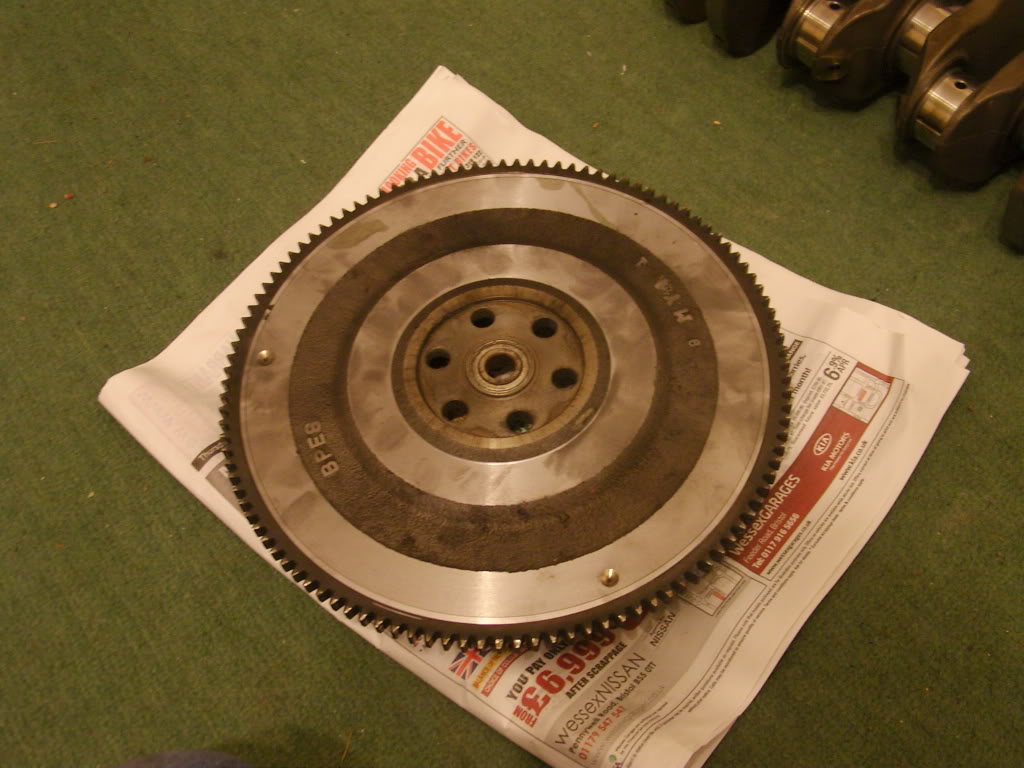
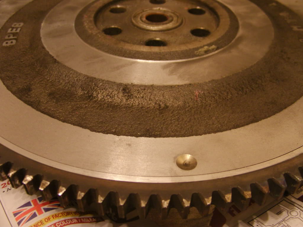
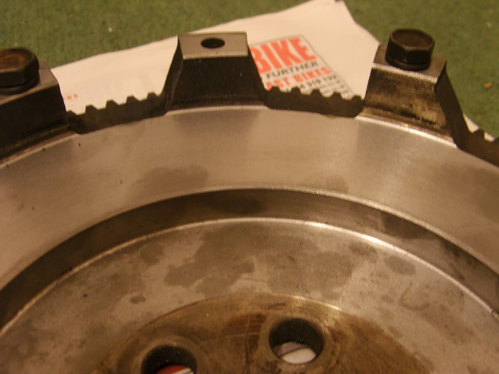
Also take a look at my now not so standard flywheel.
Spent a few hours playing on the big centre lathe at work and managed to add 4lbs of lightness (now weighs in at 16lbs, not bad for cast iron) with possibly more to come if I feel the need. Now I just need to balance it.
In other news unfortunately I won't be getting +1mm valves atm. I bought some second hand from pschmidt that he pulled from a spare head but unfortunately despite his machinists assurances, they're toast. He has been very kind and refunded the total amount despite me telling him to keep the shipping costs (thank you very much Patrick).
The reason I bring this to peoples attention is they are toast in a very abnormal way and I really want to know what happened to them. The exhaust valves look reasonable, there is no shiny seat margin on them but they look like they might lap in or at a push need grinding. But the inlet valves are frazzled. All of them have grooves in the seats and on some the outer 0.5mm has been completely eroded.
WTF happened!? I have never known intake valves to go before the exhaust.
Also take a look at my now not so standard flywheel.
Spent a few hours playing on the big centre lathe at work and managed to add 4lbs of lightness (now weighs in at 16lbs, not bad for cast iron) with possibly more to come if I feel the need. Now I just need to balance it.
Reply
0
0

Thread
Thread Starter
Forum
Replies
Last Post
Jike Spingleton
Cars for sale/trade
3
09-20-2016 04:33 PM
SuperSneakySecretSquirrel
Meet and Greet
5
09-06-2015 08:30 PM
Motorsport-Electronics
ECUs and Tuning
0
09-05-2015 08:02 AM


