
PNPAdurino AFM Eliminator
 07-06-2011, 03:57 PM
#1
Newb
Thread Starter

Join Date: Aug 2009
Posts: 35
Total Cats: 0
Broken out into a seperate thread so as not to take the Arduino ECU one too far off track.

Concept is to make a "box" which takes in a MAP sensor input (and others if required) and outputs an analog signal to substitute the AFM signal expected by the NA MX5 OEM ECU.
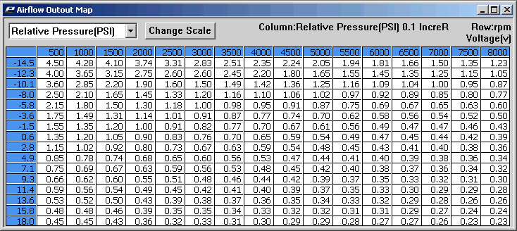
The AFM is a vane type with a potentiometer. (anyone got flow vs voltage curve?) It is inverted, low air flow generates a high voltage, high air flow / RPM generates a low voltage.
It also appears logarithmic, the change in voltage is much greater between 2000 - 4000rpm, than 5000 - 6000rpm.
Introduction "story":
I was shown an article in a magazine where the a MAP sensor and a simple inverting op amp circuit was used to substitute the AFM for a carburettor converted MX5. (so the standard ignition system would still work)
I didn't believe it could be that simple so I wired the OEM AFM to a spare ADC on the megasquirt, did some drives and used the collected data to make a curve. This is what it looks like: (I think with some averaging / smoothing applied. I need to search for the origional files.)
EG:

This is just a dumb comparative measurement based on a datalog to make a replacement curve.
The area of 15 - 25kpA is where it is too ambiguous to rely on MAP data alone, another sensor input (eg TPS, RPM, drpm/dt) is required to decide what voltage feedback is required to replicate what the AFM does.
Some additional datalogs:


I am on overseas assignment in Germany, and my MX5 is in storage in Australia so I cannot make any more logfiles.
Concept is to make a "box" which takes in a MAP sensor input (and others if required) and outputs an analog signal to substitute the AFM signal expected by the NA MX5 OEM ECU.
The AFM is a vane type with a potentiometer. (anyone got flow vs voltage curve?) It is inverted, low air flow generates a high voltage, high air flow / RPM generates a low voltage.
It also appears logarithmic, the change in voltage is much greater between 2000 - 4000rpm, than 5000 - 6000rpm.
Introduction "story":
I was shown an article in a magazine where the a MAP sensor and a simple inverting op amp circuit was used to substitute the AFM for a carburettor converted MX5. (so the standard ignition system would still work)
I didn't believe it could be that simple so I wired the OEM AFM to a spare ADC on the megasquirt, did some drives and used the collected data to make a curve. This is what it looks like: (I think with some averaging / smoothing applied. I need to search for the origional files.)
EG:
This is just a dumb comparative measurement based on a datalog to make a replacement curve.
The area of 15 - 25kpA is where it is too ambiguous to rely on MAP data alone, another sensor input (eg TPS, RPM, drpm/dt) is required to decide what voltage feedback is required to replicate what the AFM does.
Some additional datalogs:
I am on overseas assignment in Germany, and my MX5 is in storage in Australia so I cannot make any more logfiles.
Last edited by FieldEffectDave; 07-06-2011 at 05:31 PM.

Reply
 0
0

0
07-06-2011, 06:59 PM
#2
Boost Pope


iTrader: (8)
Join Date: Sep 2005
Location: Chicago. (The less-murder part.)
Posts: 33,456
Total Cats: 6,874
Yeah, I did this about five or six years ago using a Greddy E-Manage Ultimate. Here's the writeup I did on it: http://miatajoe.50megs.com/
There's a complete graph of sensor voltage vs. RPM for different MAP readings, along with all the raw data behind it. Lots of other details as well.
There's a complete graph of sensor voltage vs. RPM for different MAP readings, along with all the raw data behind it. Lots of other details as well.

Reply
0
0
07-06-2011, 08:12 PM
#3
Elite Member

Join Date: Jul 2005
Posts: 6,420
Total Cats: 84
I have an Arduino box that does this.
Takes 2001 cam and 12+1 crank inputs, and MAP sensor as inputs, and puts out the following:
MAF signal
factory crank signal
to feed the factory ECU so it'll do the emissions, EGR, and idle properly.
The MAF signal is a function of MAP and RPM. To do it properly, I did a 3D curve fit of the MAF signal datalogs.
Reply
0
0
07-07-2011, 03:23 AM
#4
Newb
Thread Starter
Join Date: Aug 2009
Posts: 35
Total Cats: 0
Thanks for that Joe!!!!!!!
Would not be hard at all to implement this in an Arduino.
I don't quite follow the AE table on your page.
For an acceleration enrichment input, could the derivative of the MAP sensor signal be used?
Would not be hard at all to implement this in an Arduino.
I don't quite follow the AE table on your page.
For an acceleration enrichment input, could the derivative of the MAP sensor signal be used?
Last edited by FieldEffectDave; 07-07-2011 at 10:40 AM.
Reply
0
0
07-07-2011, 11:38 AM
#5
Boost Pope
iTrader: (8)
Join Date: Sep 2005
Location: Chicago. (The less-murder part.)
Posts: 33,456
Total Cats: 6,874
The E-Manage did not directly support the use of MAP as an enrichment trigger- the software only allowed you to use TPS. Of course, that car (at the time) did not have an analog TPS, so I connected the output of the MAP sensor to the TPS input of the E-Manage (this was a fairly common technique), so the end result was that the MAP sensor was used, but in a non-intuitive way.
I personally believe that a true TPS signal is probably a better signal to use than MAP, since sudden throttle movements should (in theory) be reflected in the TPS signal slightly quicker than they are in the MAP signal. It takes time (albeit not very much) for the pressure inside the manifold and the tubing between the manifold and sensor to equalize after the throttle plate has moved.
Good luck with your project. Out of curiosity, may I ask why you are doing this? For my own car, I chose to rip out the entire system and replace it with a MegaSquirt as soon as the technique for doing so became commonly supported on the Miata (I was tired of being a pioneer), and I was quite happy with the result.
I love your username, by the way. Maybe mine should be Bipolar Junction Joe?

Reply
0
0
07-07-2011, 12:13 PM
#7
Boost Pope
iTrader: (8)
Join Date: Sep 2005
Location: Chicago. (The less-murder part.)
Posts: 33,456
Total Cats: 6,874
Heh. I didn't even think of that one.
In the US, "bipolar" means that you have a psychiatric (mental) illness which causes frequent and uncontrollable mood changes, alternating between depression and mania. In other words, a biploar person is ******* crazy (though also quite likely to be a successful artist or musician.)
http://en.wikipedia.org/wiki/Bipolar_disorder
Reply
0
0
07-07-2011, 02:07 PM
#10
Newb
Thread Starter
Join Date: Aug 2009
Posts: 35
Total Cats: 0
Out of curiosity, may I ask why you are doing this?
So I want this level of redundancy, and also to remove the AFM.
I guess the next question is, what happens if the Arduino AFM substitute ***** itself. So long as it doesn't die at the same time as the megasquirt I will be fine. Maybe ill keep the AFM in the boot : /
Last edited by FieldEffectDave; 07-07-2011 at 02:19 PM.
Reply
0
0
07-07-2011, 07:18 PM
#11
Newb

Join Date: Apr 2010
Posts: 10
Total Cats: 0
My MX5 is a daily drive and I am abit paranoid. I want to move from a shared function boomslang to a stand alone setup, but I want the security blanket that if the Megasquirt smokes I can pull the carpet and swap the OEM PCM back in at any stage. And drive around on the OEM PCM until I have the time to investigate problems.
So I want this level of redundancy, and also to remove the AFM.
I guess the next question is, what happens if the Arduino AFM substitute ***** itself. So long as it doesn't die at the same time as the megasquirt I will be fine. Maybe ill keep the AFM in the boot : /
So I want this level of redundancy, and also to remove the AFM.
I guess the next question is, what happens if the Arduino AFM substitute ***** itself. So long as it doesn't die at the same time as the megasquirt I will be fine. Maybe ill keep the AFM in the boot : /
the stand alone units are a cool thing when you want to go big. but i just don't want to spend $250 for a complete DIY megasquirt setup or 450 for the pnp setup. i don't want to spend that much money. i don't know what it is.. but i just don't want to sink my hands into megasquirt. i mean they make a great product. but like in the late 90's i just want to be a part of a community who came up with a program like Crome for P28's that there was for the most part a community effort. i wish we could do the same thing for our cars. our cars deserve it.
any case spending $113 for audrino or mbed makes me feel like a Jewish Diamond Smuggler who struck rich. i don't mind doing something the helps out a whole community which does including myself. that is mostly my perspective.
btw back to topic question:
should we follow the other threads group on using mbed? the other thread had already ported the code and it should function with ease. it really is a superior hardware. should we consider this hardware instead of audrino?
also push comes to shove if anyone wanted to go stand alone from the "AFM Eliminator". the base hardware is there to change over accordingly. we should have design a way where we can reflash, recode and reconfigure hardware if a person wanted to have full control.
literally we could customize the way we want to tune the car.
but i don't want to thread this thread to think that it's an obsolete idea. i am still very interested in putting a working product in my car.
Reply
0
0
07-08-2011, 05:06 AM
#12
Newb
Thread Starter
Join Date: Aug 2009
Posts: 35
Total Cats: 0
should we follow the other threads group on using mbed?
I would go for an Arduino / Atmel, maybe even an ATTINY. Built with discrete components, an onboard MAP sensor (the one MS uses is $14 from digikey) and parts scabbed from the old AFM I would aim for a $50 DIY build price.
Electronics design question:
I would probably do the D2A with a resistor ladder, maybe start with 8 bits.
I want the ground return of the D2A to use the signal ground from the OEM PCM - so there is no risk of a ground shift between our "box" and the OEM PCM causing an error in the signal voltage.
I want the Arduino / powersupply ground return to be a seperate chassis return, so the Arduino supply current is not returning through the OEM PCM signal ground.
How can achieve the ground isolation between the D2A output ground and the Arduino ground?
I was thinking of using the AFM pot supply from the PCM as a VREF - maybe divide by 2 with a low tolerance resistive divider feed into an A2D then do ratio metric scaling of the output based on this measurement. But the difference between ARduino AREF / VCC and the OEM PCM Signal output is probably going to be so small this would be a waste of time? Thoughts?
Last edited by FieldEffectDave; 07-08-2011 at 05:16 AM.
Reply
0
0
07-08-2011, 08:30 AM
#13
Junior Member

Join Date: Sep 2010
Location: London, England
Posts: 91
Total Cats: 0
This does sound like a fun project! I'll keep tabs on it and help where I can!
@blade8r while the Mbed is lovely, with loads of great features... It does cost twice as much and an Arduino and it is a 3.3volt system, not really a problem for digital parts of the system... But a bit of a pain in the wotsit for the 5volt analogues in the car
@FieldEffectDave, why use an DAC at all? A resistor ladder is easy to build and 8bit resolution would be sufficient for this project... But... That eats up 8 IO pins... If it was me building this I would use a single PWM output with a simple RC filter to average the voltage out any problems with that? (also did you get my PM?)
@blade8r while the Mbed is lovely, with loads of great features... It does cost twice as much and an Arduino and it is a 3.3volt system, not really a problem for digital parts of the system... But a bit of a pain in the wotsit for the 5volt analogues in the car
@FieldEffectDave, why use an DAC at all? A resistor ladder is easy to build and 8bit resolution would be sufficient for this project... But... That eats up 8 IO pins... If it was me building this I would use a single PWM output with a simple RC filter to average the voltage out
any problems with that? (also did you get my PM?)
Reply
0
0
07-08-2011, 09:28 AM
#14
Newb
Thread Starter
Join Date: Aug 2009
Posts: 35
Total Cats: 0
http://dlnmh9ip6v2uc.cloudfront.net/datasheets/Components/General%20IC/22060b.pdf
I am actually thinking something like this would be ideal.
It will isolate the Arduino ground from the AFM signal ground.
Will use the PCM signal supply - so no compensation required there if the Arduino VCC/AREF differs from the PCM Sensor supply.
Can be chosen to a similar impedance to the AFM potentiomer - which should provide good compatibility with the PCM input circuit.
Yep. I need to get another PCM so I can run it on the bench to continue following the traces back to the uC.
I am actually thinking something like this would be ideal.
It will isolate the Arduino ground from the AFM signal ground.
Will use the PCM signal supply - so no compensation required there if the Arduino VCC/AREF differs from the PCM Sensor supply.
Can be chosen to a similar impedance to the AFM potentiomer - which should provide good compatibility with the PCM input circuit.
also did you get my PM?
Last edited by FieldEffectDave; 07-08-2011 at 09:42 AM.
Reply
0
0
07-08-2011, 09:57 AM
#15
Junior Member
Join Date: Sep 2010
Location: London, England
Posts: 91
Total Cats: 0
http://dlnmh9ip6v2uc.cloudfront.net/datasheets/Components/General%20IC/22060b.pdf
I am actually thinking something like this would be ideal.
It will isolate the Arduino ground from the AFM signal ground.
Will use the PCM signal supply - so no compensation required there if the Arduino VCC/AREF differs from the PCM Sensor supply.
Can be chosen to a similar impedance to the AFM potentiomer - which should provide good compatibility with the PCM input circuit.
I note that the Arduino can take an external voltage ref (as long as it's not above 5v).
Though, more components always leads to more points of failure... Something that I'm always very conscious of when designing systems.
Yep. I need to get another PCM so I can run it on the bench to continue following the traces back to the uC.
the more I think about the Coolant temp signal, the more I'm convinced the IC blocking your path is just a comparator, the ECU knows the engine is either Hot (at working temp) or cold (below working temp).
Reply
0
0
07-08-2011, 12:32 PM
#16
Boost Pope
iTrader: (8)
Join Date: Sep 2005
Location: Chicago. (The less-murder part.)
Posts: 33,456
Total Cats: 6,874
2A: Injector ground
2B: Output ground (things like IAC and solenoids)
2C: CPU ground
2D: Input ground (sensor ground)
2A and 2B are tied together and then go to the head at Ground Point 3.
2C and 2D also tie together and hit the head at Ground Point 2. Communally, they also provide the ground path for the shield on the O2 sensor line, the shield on the AFM signal line, and the grounds for TPS, AFM (VAF and IAT, but not COR) and CLT.
(That may be the largest number of TLAs ever written in a single sentence.)
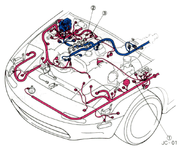
Here's the page from the '92 FSM which shows all of the relevant ECU grounds schematically:
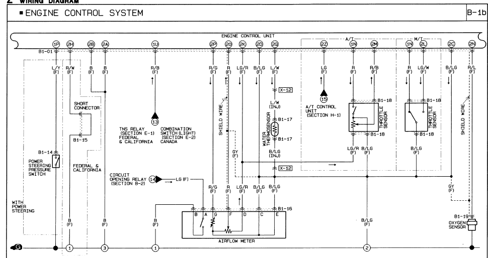
And the drawing which shows the locations of ground points 2 and 3:
I'm not clear on the purpose of the ground at 2H. The FSM simply states that the little jumper is present in US cars, and presumably absent in Canada cars. The jumper itself is under the dash near the point where the front harness comes in through the firewall on the passenger's side, and ground point 1 looks to be just to the right of the HVAC fan. I would avoid it.
Reply
0
0
07-08-2011, 12:53 PM
#17
Newb
Thread Starter
Join Date: Aug 2009
Posts: 35
Total Cats: 0
Was more a question of electronic design:
With PWM + RC, Resistor Ladder etc, ... output voltage will be referenced to Arduino ground. If you tie Arduino ground to the AFM ground on the PCM then your Arduino return current will add a voltage shift / noise on the ground wire and potentially affect the measurement made by the PCM.
Its probably being over ----, but best practices would be to avoid this. Hence the digital pot makes a neat solution:

Does anyone know what the full deflection impedance of the AFM pot is?
With PWM + RC, Resistor Ladder etc, ... output voltage will be referenced to Arduino ground. If you tie Arduino ground to the AFM ground on the PCM then your Arduino return current will add a voltage shift / noise on the ground wire and potentially affect the measurement made by the PCM.
Its probably being over ----, but best practices would be to avoid this. Hence the digital pot makes a neat solution:
Does anyone know what the full deflection impedance of the AFM pot is?
Last edited by FieldEffectDave; 07-08-2011 at 01:13 PM.
Reply
0
0
07-08-2011, 01:14 PM
#18
Elite Member
Join Date: Jul 2005
Posts: 6,420
Total Cats: 84
FED you are overcomplicating things.
The Arduino doesn't suck a lot of current so its power supply return current can be connected to its analog output filter return, and all connected to the ECU's sensor ground. Just be sure to properly decouple the uC and any other digital circuitry locally on its board. BTDT. I used the Arduino PWM "analog" output into an opamp 2-pole lopass filter. The miata has stuff that sinks much more current into the sensor ground.
If you insist on a separate ground:
All you need to do to have a separate analog output ground is to use the Arduino PWM "analog" output to drive a small signal MOSFET which drives the lopass filter. The small signal MOSFET switch will ignore any ground offsets between the uC ground and the analog circuit ground.
I do this grounding **** for a living. I design switching power supplies. You have circuitry that switches 10A and 500V in 20 ns sitting next to ground signals with 10 mv of discrimination.
Reply
0
0
07-08-2011, 01:25 PM
#19
Boost Pope
iTrader: (8)
Join Date: Sep 2005
Location: Chicago. (The less-murder part.)
Posts: 33,456
Total Cats: 6,874
I like the digital pot idea simply because a monolithic D-A converter is cleaner than some resistor-ladder combination.
I cannot imagine, however, that a teeny little arduino and the tiny little signals that it's dealing with are going to cause any kind of noise that could possibly be perceived beneath all the garbage that's already present in most of the ECU's I/O lines as a result of their close physical proximity to things like the injector wiring.
Reply
0
0
07-08-2011, 01:53 PM
#20
Newb
Thread Starter
Join Date: Aug 2009
Posts: 35
Total Cats: 0
Fair enough, thanks for the insights!
Just tossing around more design ideas:
Inside the PCM the Sensor supply (2K) comes straight from VCC, via this device:

Which could be a hybrid thermal fuse + pi filter?
I put ~90 Ohms of load on the output and had the heat gun set to 120 degrees (C) aimed at the fuse and there was no voltage drop across it.
(~47ohms + 80 degrees on the gun was enough for the fuse to trip.)
So provided the circuit can stick within a current budget of say 40mA it could be powered off the sensor supply and then no additional power / ground is required and drops a few components off the BOM.
Just tossing around more design ideas:
Inside the PCM the Sensor supply (2K) comes straight from VCC, via this device:
Which could be a hybrid thermal fuse + pi filter?
I put ~90 Ohms of load on the output and had the heat gun set to 120 degrees (C) aimed at the fuse and there was no voltage drop across it.
(~47ohms + 80 degrees on the gun was enough for the fuse to trip.)
So provided the circuit can stick within a current budget of say 40mA it could be powered off the sensor supply and then no additional power / ground is required and drops a few components off the BOM.
Reply
0
0


