When you click on links to various merchants on this site and make a purchase, this can result in this site earning a commission. Affiliate programs and affiliations include, but are not limited to, the eBay Partner Network.
I've been doing some reading about wiring up my oil temperature sensor. Maybe it's obvious and I'm just misunderstanding, but I can't seem to get it working properly. I would really appreciate it if someone could spell out exactly how to wire it and set it up properly. If this has already been done elsewhere, I must've missed it and a link would be very helpful. I've read though this thread, but he uses a different sensor.
I'm using. I have the sensor installed in a sandwich plate on the oil filter.
I have a 99 MS3Pro PNP from DIYAutotune and Tunerstudio.
The information that I'm specifically looking for is:
1. Which pin on the MS accessory harness should the signal wire be pinned to?
2. Which settings in TunerStudio need to be changed to make it work? What should their new values be?
Right now I have it on Analog Input 2 and GM Calibration. Doesn't seem to be working.
I don't know how the pins are allocated, but I can tell you that you will need to add a pull-up resistor to your harness.
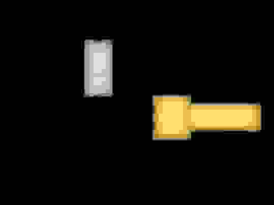
A pull-up resistor (more on MSExtra here) goes between the 5V reference signal and your analog input; together with the variable resistance of the temperature sensor, it makes a resistive "voltage divider" that allows the ECU to see a voltage that varies predictably with temperature.
The standard convention for MS ECUs is a 2.49kΩ resistor between 5V and the analog input. The sensor is not sensitive to polarity, so either wire is fine.
Okay, thanks for that. I've been doing some more reading and I think I understand better now. The wiring diagram is also very helpful.
Please excuse my electrical ignorance, but is it important that the resistor be 2.49kΩ? Or is a different resistance okay? Based on my searching seems somewhat hard to find 2.49kΩ. Does anyone have a good place to buy them?
For anyone coming to this thread later, I figured that I'd consolidate some more information.
First, it is important that the resistor is 2.49kΩ.
The resistors can be found here on DIYAutotune. The resistors are cheap, but the shipping is incredibly expensive if you're just buying the resistors.
I found the same resistors here on eBay for a lot less money for many more resistors.
I believe that the wiring diagram posted above is correct. For reference, I have reposted it below.
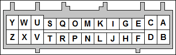
Additionally, here are the pins that should be connected on the 26 pin options connector.
5V VREF - H
Analog In 2 - C
GND - A
With any luck, parts should get here this weekend and I'll try to report back if everything works correctly now.
 11-30-2019, 09:06 PM


 0
0