
Wiring Honda B18c Tps for use on MSM w/hydra
 07-06-2012, 12:14 AM
#1
Senior Member
Thread Starter
iTrader: (3)

Join Date: May 2008
Location: Fargo, ND
Posts: 533
Total Cats: 3
Anybody have a wiring diagram for a tps out of an integra at all so that I can run a Honda TPS in the MSM setup? I've got a honda intake manifold and throttle body on my bp motor and need to figure something out for wiring and make a plug to mate this stuff up together to work with the hydra and such. Other than that its working out pretty well.
I have not yet come up with a good way to keep the variable tps setup, but I guess that's not the hugest of deals at the moment.
Any help would be appreciated. I'm working through my 04 MSM wiring diagram right now.
Thanks,
Nick
I have not yet come up with a good way to keep the variable tps setup, but I guess that's not the hugest of deals at the moment.
Any help would be appreciated. I'm working through my 04 MSM wiring diagram right now.
Thanks,
Nick

Reply
 0
0

0
07-06-2012, 11:01 AM
#2
Senior Member
Thread Starter
iTrader: (3)
Join Date: May 2008
Location: Fargo, ND
Posts: 533
Total Cats: 3
digging a bit on my own here is the wiring for the honda stuff. I think our signals don't work the same way so this may be an issue I'm going to run into.
I know a few people on here have done this so someone must know the answer.
The Official Honda TPS wiring and calibration thread - Honda-Tech
I know a few people on here have done this so someone must know the answer.
The Official Honda TPS wiring and calibration thread - Honda-Tech
Reply
0
0
07-06-2012, 11:08 AM
#3
Boost Czar


iTrader: (62)
Join Date: May 2005
Location: Chantilly, VA
Posts: 79,729
Total Cats: 4,126
I dont see why it wouldn't work the same. it's a 5v variable singal, shoudl easily be able to wire it right into the stock harness exactly like the oem tps is and then just calibrate it with the hydra.
Reply
0
0
07-06-2012, 11:26 AM
#4
Senior Member
Thread Starter
iTrader: (3)
Join Date: May 2008
Location: Fargo, ND
Posts: 533
Total Cats: 3
Ok. sounds good then. I need to go back over to my car today and Find out which is the 5v input signal wire on the car harness, but I am not sure which way the other two go.. Suppose trial and error works but if anyone knows the correct way, it would help. I have a mitchell's wiring diagram that is sort of a pain in the ***, As it doesn't really tell you what I need to know. Helpful at least.
Reply
0
0
07-06-2012, 04:27 PM
#6
Senior Member
Thread Starter
iTrader: (3)
Join Date: May 2008
Location: Fargo, ND
Posts: 533
Total Cats: 3
If you guys don't here is a very very usefull link from the MSM forum with quite a few nice pdfs. Tech.zip comes in as a folder with various pdfs for the MSM and some 2000 stuff as well.
that last pdf you had was a help adding that to my wiring diagram I came up with this:
Wires at the plug as follows
Tested 5.0v at Light Green/Red wire constant volts from ecu
Black/Red ground wire
Green/Black wire Variable signal to ECU
Thanks for the tip there Brain. I'm really loathe to do anything right now, I'd prefer to just do nothing on my vacation.
Last edited by chance91; 07-06-2012 at 05:09 PM.
Reply
0
0
07-07-2012, 11:56 AM
#8
Senior Member
Thread Starter
iTrader: (3)
Join Date: May 2008
Location: Fargo, ND
Posts: 533
Total Cats: 3
Agreed. I'd been at work for 20 days until this Thursday. Good check and all but sorta drawn out.
Either way, I would like my Miata to run well, finally, so I'm holding myself to this. I'll get some photos of the work and soldering later. I gutted my OEM tps to use for the plug to the OE miata harness.
I also found out I have a 65mm throttle body when I bought this motor, neat. I like the Skunk2 manifold setup, should be quite a bit better than the oem Vtcs bullshit.
Reply
0
0
07-08-2012, 12:18 AM
#9
Senior Member
Thread Starter
iTrader: (3)
Join Date: May 2008
Location: Fargo, ND
Posts: 533
Total Cats: 3
Got the project done today, thanks for the assistance Brain.
Here's a few photos, but with the diagrams I put up earlier should be self explanatory.
I gutted the oem tps, and used a Honda wiring harness from an accord, about 96. The wiring colors are similar across the board from b16s 18s and my find, an f20 or something.
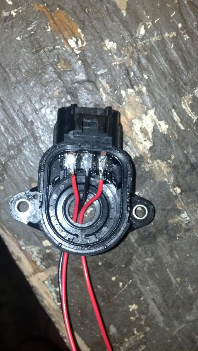
Gutted TPS all soldered up.
Basically, as mentioned, here's the wiring for an 05:
Miata ------------- Honda
LtGrn/red ------- Yellow ------ 5.0v power
Blk/red ------------ Green ------ Sensor Ground
Green/Blck ------ Red ------ ECM Signal
Run the wires up through the bottom hole of the TPS, and solder them to the small metal spots there. You have to lift the little tabs up and out of the way, you can put them back after soldering.
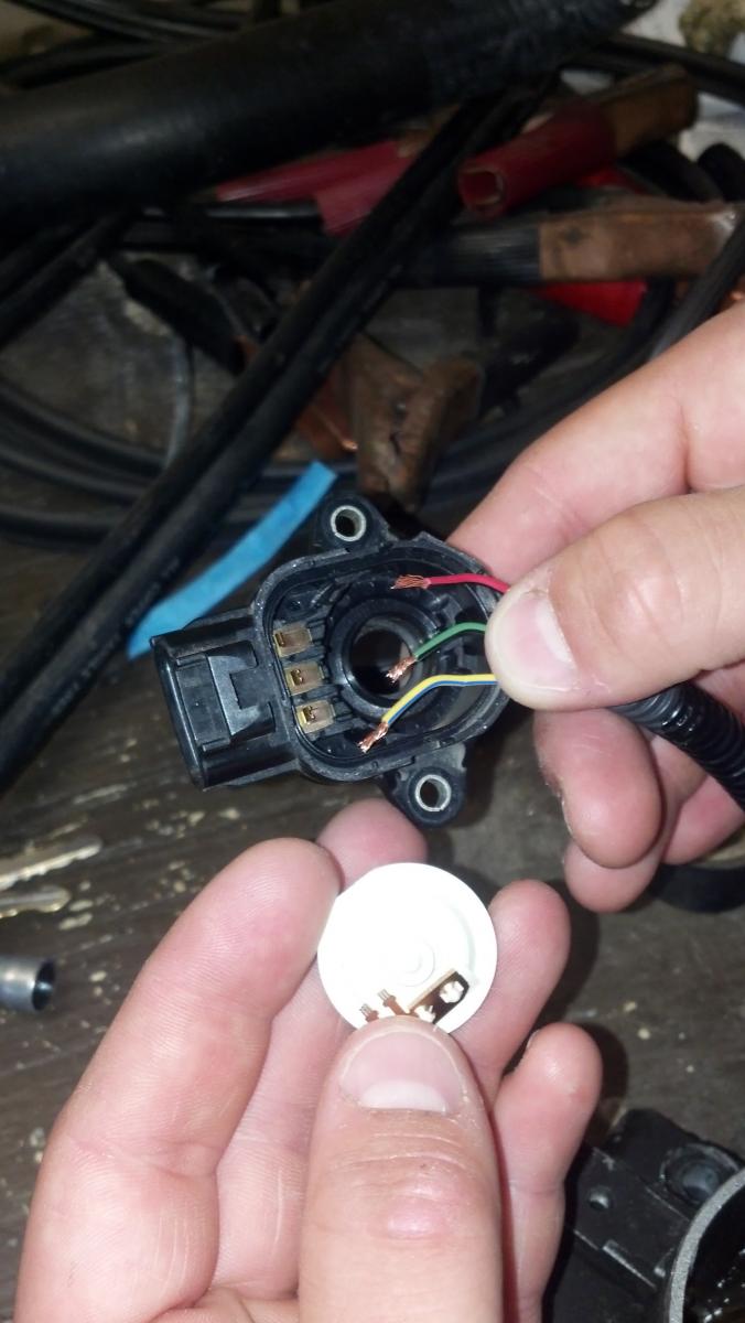
Here is the layout of the TPS points and honda wires in the right order.
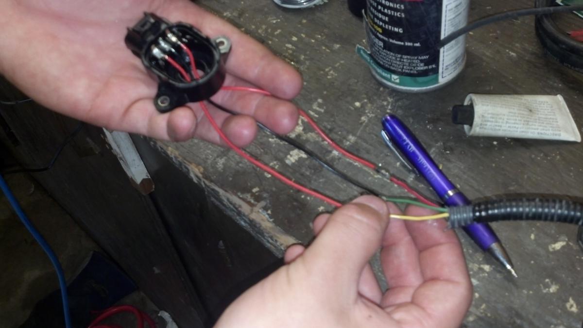
All wired up. Had to extend the harness out.
Super glue or what have you it together, and you are good to go.
Should be an easy mod, and I tested it in my Hydra, everything was right.
Here's a few photos, but with the diagrams I put up earlier should be self explanatory.
I gutted the oem tps, and used a Honda wiring harness from an accord, about 96. The wiring colors are similar across the board from b16s 18s and my find, an f20 or something.
Gutted TPS all soldered up.
Basically, as mentioned, here's the wiring for an 05:
Miata ------------- Honda
LtGrn/red ------- Yellow ------ 5.0v power
Blk/red ------------ Green ------ Sensor Ground
Green/Blck ------ Red ------ ECM Signal
Run the wires up through the bottom hole of the TPS, and solder them to the small metal spots there. You have to lift the little tabs up and out of the way, you can put them back after soldering.
Here is the layout of the TPS points and honda wires in the right order.
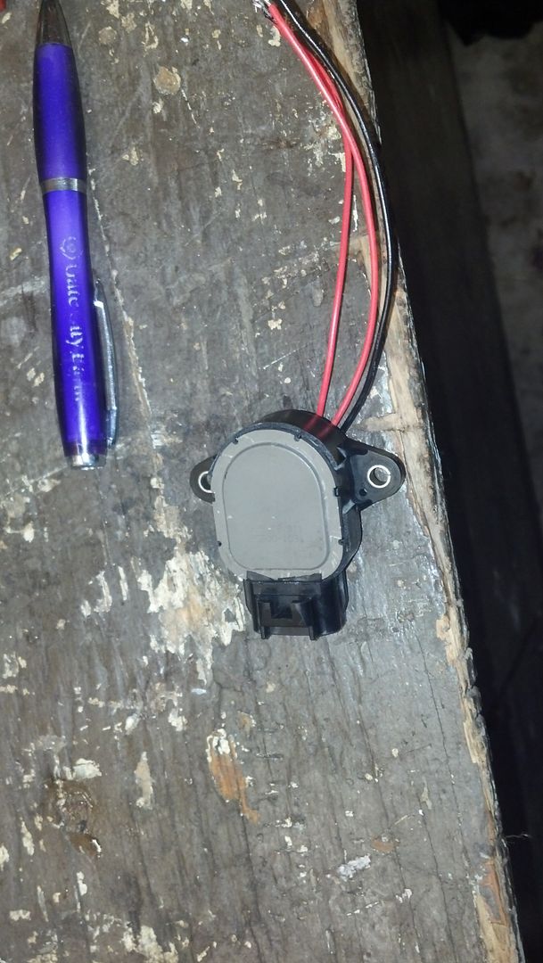
All wired up. Had to extend the harness out.
Super glue or what have you it together, and you are good to go.
Should be an easy mod, and I tested it in my Hydra, everything was right.
Reply
0
0

Thread
Thread Starter
Forum
Replies
Last Post


