
Toyota COP dwell curve

 04-07-2012, 12:44 AM
#62
Elite Member
Thread Starter

Join Date: Jul 2005
Posts: 6,420
Total Cats: 84
Here are the specs for the Toyota COPs with part number 90919-02246
Primary inductance is 3.7 mH up to 7A;
From 7-12A, 1.4 mH
It current limits just below 12 A
In order to hit 10A, you need the following dwell numbers
V mS
15 2.1
14 2.3
12 3.1
10 4.3
To hit 7A, you need
V ms
15 1.75
14 1.9
12 2.45
10 3.2
The turns ratio appears to be around 80:1
At 12A of primary current, peak secondary current is 140 mA
With a 1kV TVS (zener) load, the spark duration is 1.2 to 1.3 ms for a dwell current of 7-12A. (Stays pretty constant, but max voltage should be higher)
Secondary spark energy is 58 mJ at 12A of primary current
At 10A it's 55 mJ
At 7A it's 45 mJ.
The trigger input impedance is about 350 ohms.
It needs a minimum of 2.5V to dwell, and must go below 2V to fire.
It can be driven from 5V or from 12V, as long as the drive current is at least 7 mA.
At just 4.4A of dwell current the output reaches 30 kV, and it takes 45us to get there.
At 6A of dwell current the output reaches 40 kV, and that's the limit of my 1000x probe.
Takes 40 us to get there.
The delay time from trigger to when the output begins to rise is 8us.
At 7A of dwell current, the output rise time is 8 us.
At 10A, it's 10 us.
Here's the comparo against other coils:
https://www.miataturbo.net/showpost....9&postcount=53
These look like strong coils.
I think these are the ones to have.
Last edited by JasonC SBB; 04-07-2012 at 03:10 PM.

Reply
 0
0

0
04-08-2012, 03:18 PM
#67

If you're asking what motor you can find these in from factory its toyota's v6 3MZFE which is: CAMRY'S V6, 2004-2008, SOLARAS, V6 2002-2008, HIGHLANDERS 2002-2008 & LEXUS ES330 2004-2008, RX330 2004-2008.
The shape isn't quite the same as these are a bit longer then the typical toyota cop.
Is that what you were asking?
Reply
0
0
04-09-2012, 11:54 AM
#69
DEI liberal femininity


iTrader: (8)
Join Date: Jun 2005
Location: Fake Virginia
Posts: 19,338
Total Cats: 574
it would be awesome if they were just a hair smaller diameter.
or if someone found better coils that were a hair smaller diameter.
... so they fit in the 01 valve cover.
or if someone found better coils that were a hair smaller diameter.
... so they fit in the 01 valve cover.
Reply
0
0
08-23-2012, 06:19 PM
#71
Newb

Join Date: Mar 2009
Location: Beside the beach, NSW, Oz
Posts: 4
Total Cats: 0
They were described as removed from a JDM 3.0L Toyota Harrier. I think that's sold as a Lexus RX300 in Oz and the States.
Last edited by manga_blue; 08-23-2012 at 08:20 PM.
Reply
0
0
06-03-2013, 12:47 AM
#73
Elite Member
Join Date: Mar 2007
Location: Santa Clara, CA
Posts: 5,181
Total Cats: 858
...bringing this thread back from the dead again.
A friend and I o-scope'd my COPs today. We didn't want to buy the $350 inductive current probe at Fry's, so current was measured by inserting a .05 ohm resistor in the power wire going to the COP harness and measuring the voltage drop across it. I have the 90080-19015 coils from TSE, driving them sequentially with a Hydra 2.5.
My understanding of the operation of the coils is that +12v and ground are constantly applied, but they don't do anything until the trigger wire is pulled down by the ECU. That starts the coil charging, and when the trigger is released the coil fires. As it charges, the current going into the coil rises to a max, then gets limited at that level by the internal circuitry. The dwell time is the length of time that the trigger is held down by the ECU, and it needs to be long enough to get the coil properly charged, but not too long or it overheats them. Is that right?
The Hydra has a 2d table for the dwell time, indexed by voltage, and I have set ranging from 2.5ms at around 11v to 2.0ms at 15v.
At the 2.2ms that it was using while idling, the max current we saw on the scope was 3A. This seemed awfully low, given the 10A numbers I saw in this thread and elsewhere, so I tried increasing it. More dwell gave more current up to 5.0 ms where I chickened out and stopped testing, afraid of frying stuff.
At 13.8 volts on the Hydra (which reads about half a volt low), the results looked like this (argh, is there a better way to make a decent looking table in the forum syntax?):
dwell (nominal, ms) dwell (measured, ms) current (amps)
2.2 ------------------ 2.25 ------------------- 2.99
2.5 ------------------ 2.56 ------------------- 3.56
3.0 ------------------ 3.06 ------------------- 4.50
3.5 ------------------ 3.58 ------------------- 5.56
4.0 ------------------ 4.08 ------------------- 6.28
4.5 ------------------ 4.54 ------------------- 6.90
5.0 ------------------ 5.16 ------------------- 7.36
Here's a screenshot from the scope of the last measurement:
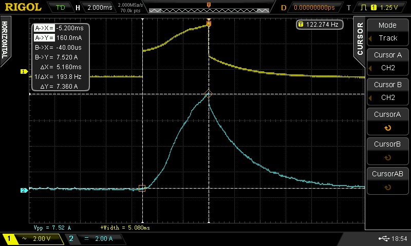
So... wtf? Am I measuring something wrong, or do these coils really want a lot more dwell than everyone else seems to be seeing? If I'm only putting 3A in them at 2.2ms, does that mean I'm only running them at 30% of their max power? If so, I'm surprised the car runs well (no misfires under boost, even at 15psi/270rwhp). We used a pair of 0.1 ohm resistors in parallel in the power line, making 0.05 ohm. Measuring a 0.15v drop across it yields 3.0 amps. Yes, the ~ 1% voltage drop from the resistor will reduce the current, but surely not by that much? We measured the current before the capacitor, which is not ideal, but that should just filter out some high frequency noise, right?
--Ian
A friend and I o-scope'd my COPs today. We didn't want to buy the $350 inductive current probe at Fry's, so current was measured by inserting a .05 ohm resistor in the power wire going to the COP harness and measuring the voltage drop across it. I have the 90080-19015 coils from TSE, driving them sequentially with a Hydra 2.5.
My understanding of the operation of the coils is that +12v and ground are constantly applied, but they don't do anything until the trigger wire is pulled down by the ECU. That starts the coil charging, and when the trigger is released the coil fires. As it charges, the current going into the coil rises to a max, then gets limited at that level by the internal circuitry. The dwell time is the length of time that the trigger is held down by the ECU, and it needs to be long enough to get the coil properly charged, but not too long or it overheats them. Is that right?
The Hydra has a 2d table for the dwell time, indexed by voltage, and I have set ranging from 2.5ms at around 11v to 2.0ms at 15v.
At the 2.2ms that it was using while idling, the max current we saw on the scope was 3A. This seemed awfully low, given the 10A numbers I saw in this thread and elsewhere, so I tried increasing it. More dwell gave more current up to 5.0 ms where I chickened out and stopped testing, afraid of frying stuff.
At 13.8 volts on the Hydra (which reads about half a volt low), the results looked like this (argh, is there a better way to make a decent looking table in the forum syntax?):
dwell (nominal, ms) dwell (measured, ms) current (amps)
2.2 ------------------ 2.25 ------------------- 2.99
2.5 ------------------ 2.56 ------------------- 3.56
3.0 ------------------ 3.06 ------------------- 4.50
3.5 ------------------ 3.58 ------------------- 5.56
4.0 ------------------ 4.08 ------------------- 6.28
4.5 ------------------ 4.54 ------------------- 6.90
5.0 ------------------ 5.16 ------------------- 7.36
Here's a screenshot from the scope of the last measurement:
So... wtf? Am I measuring something wrong, or do these coils really want a lot more dwell than everyone else seems to be seeing? If I'm only putting 3A in them at 2.2ms, does that mean I'm only running them at 30% of their max power? If so, I'm surprised the car runs well (no misfires under boost, even at 15psi/270rwhp). We used a pair of 0.1 ohm resistors in parallel in the power line, making 0.05 ohm. Measuring a 0.15v drop across it yields 3.0 amps. Yes, the ~ 1% voltage drop from the resistor will reduce the current, but surely not by that much? We measured the current before the capacitor, which is not ideal, but that should just filter out some high frequency noise, right?
--Ian
Reply
0
0

Thread
Thread Starter
Forum
Replies
Last Post
Zaphod
MEGAsquirt
47
10-26-2018 11:00 PM


