
How to Turbocharge your NA for 2k, build with TONNES of pics and info.
 07-23-2013, 11:07 AM
#41
Elite Member
Thread Starter

Join Date: Apr 2010
Location: Newcastle, Australia
Posts: 2,826
Total Cats: 67
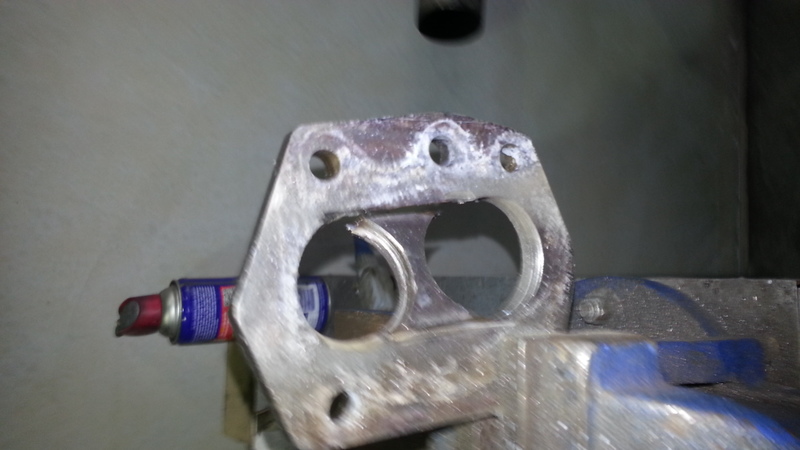
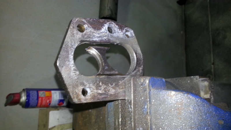
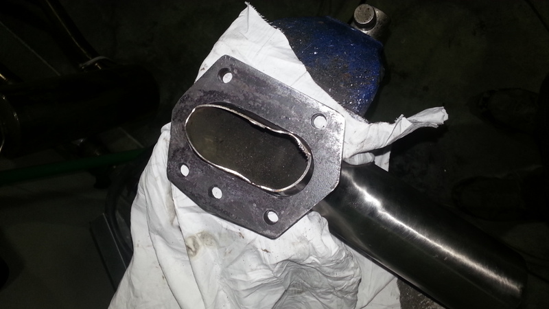
So continuing with this flange..
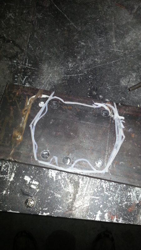
Trace a rough stencil.
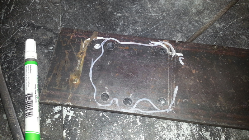
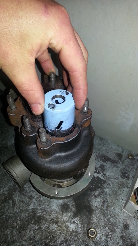
Double check you have a hole saw that matches the turbo.
Connect the edges with straight lines, this will be cut with an angle grinder.
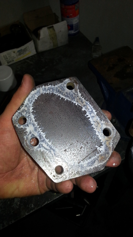
Looking ok.
Tidied up with sandpaper.
Now it looks alright.
Tonnes of spraypaint, note that I took the turbine housing off to do this.
Now we have a flange shape, we can holesaw the centre out and build a downpipe.
Dann
Trace a rough stencil.
Double check you have a hole saw that matches the turbo.
Connect the edges with straight lines, this will be cut with an angle grinder.
Looking ok.
Tidied up with sandpaper.
Now it looks alright.
Tonnes of spraypaint, note that I took the turbine housing off to do this.
Now we have a flange shape, we can holesaw the centre out and build a downpipe.
Dann

Reply
 1
1

1
 07-23-2013, 11:08 AM
#43
Elite Member
Thread Starter
Join Date: Apr 2010
Location: Newcastle, Australia
Posts: 2,826
Total Cats: 67
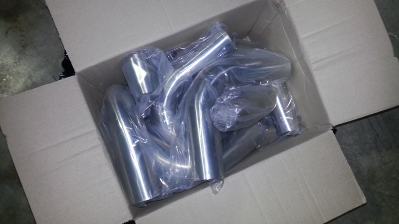
So a box of bits arrived this arvo 8)
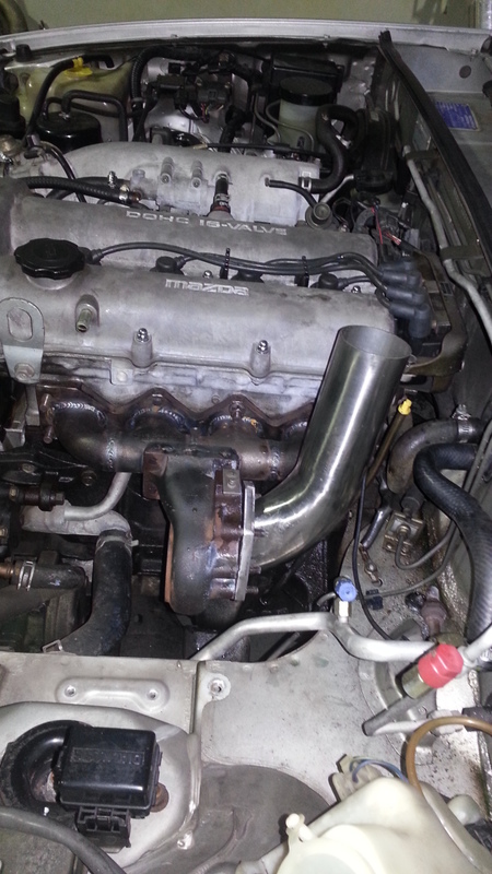
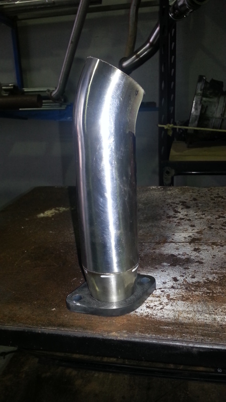
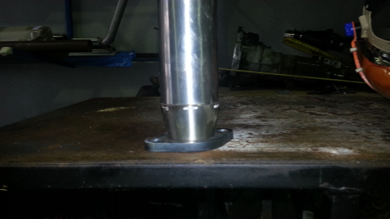
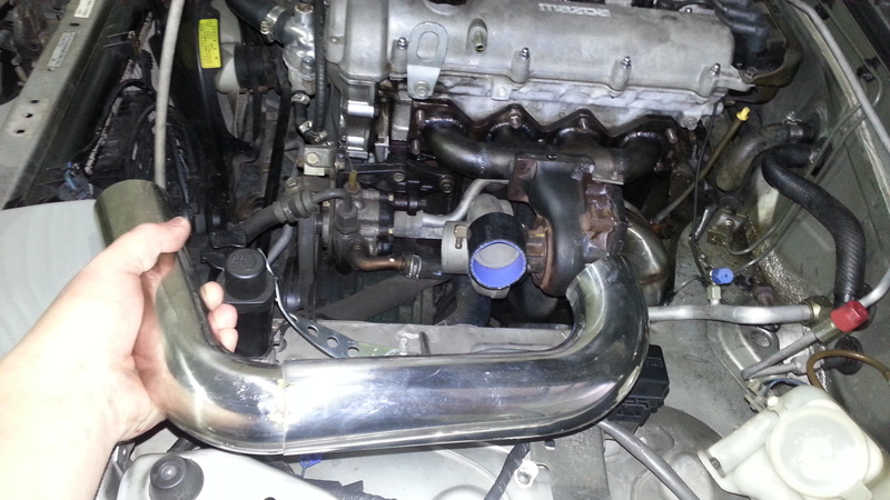
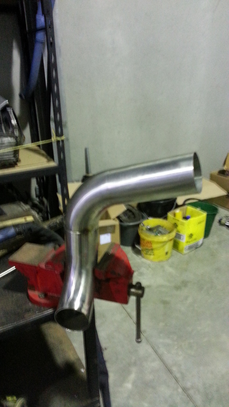
So Ive tacked the turbo to the manifold, for some test fitting and the downpipe build.
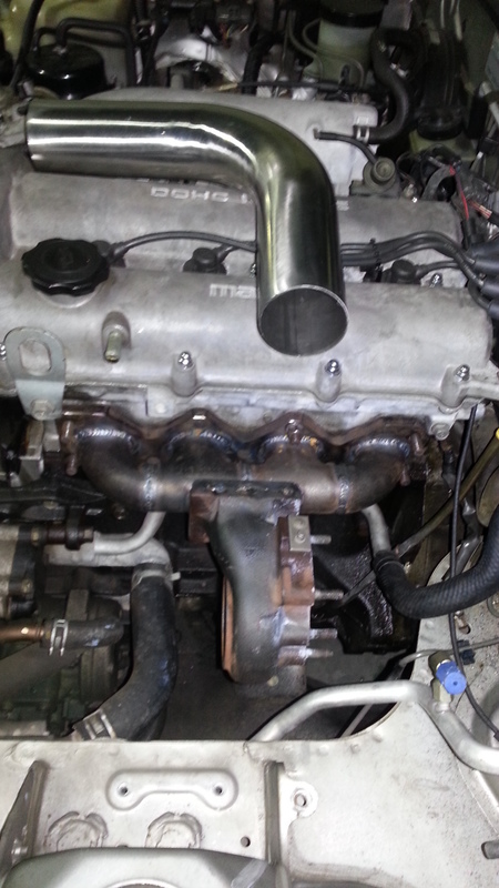
The vice will be used like this to shape the pipe initially.
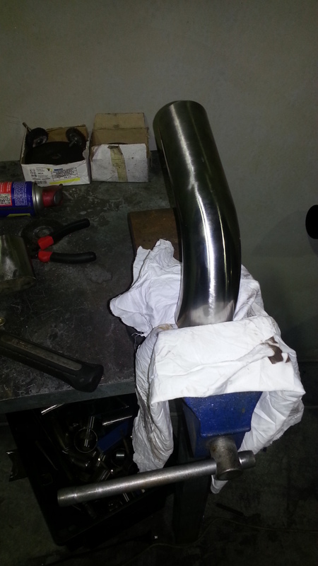
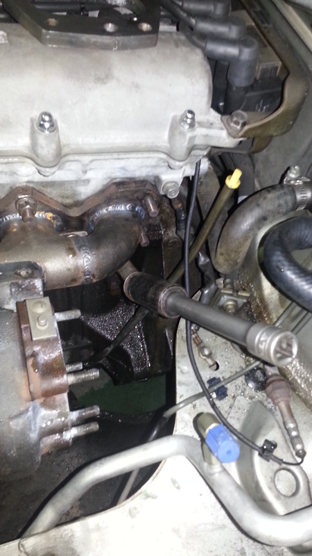
This little guy is the water return for the in cabin heater, it always gets in the road of a good downpipe.
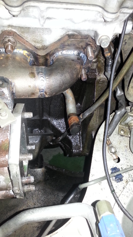
But with some gentle persuasion, it easily bends away for a little more clearance, this is standard practice on turbo NAs.
I dont suggest consulting the warranty handbook for the vice before doing this, it wont help :P
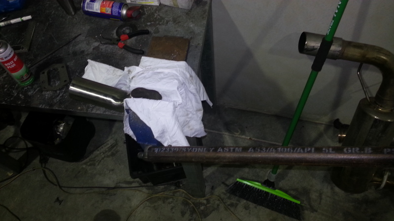
I know its ugly now but let me weld it and tidy it and away we go
Dann
So Ive tacked the turbo to the manifold, for some test fitting and the downpipe build.
The vice will be used like this to shape the pipe initially.
This little guy is the water return for the in cabin heater, it always gets in the road of a good downpipe.
But with some gentle persuasion, it easily bends away for a little more clearance, this is standard practice on turbo NAs.
I dont suggest consulting the warranty handbook for the vice before doing this, it wont help :P
I know its ugly now but let me weld it and tidy it and away we go
Dann
Reply
2
2

 07-23-2013, 11:09 AM
#45
Elite Member
Thread Starter
Join Date: Apr 2010
Location: Newcastle, Australia
Posts: 2,826
Total Cats: 67
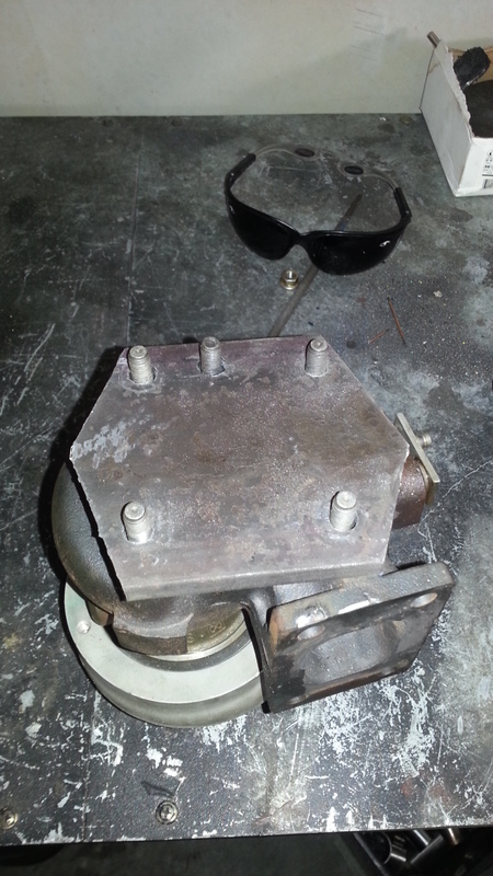
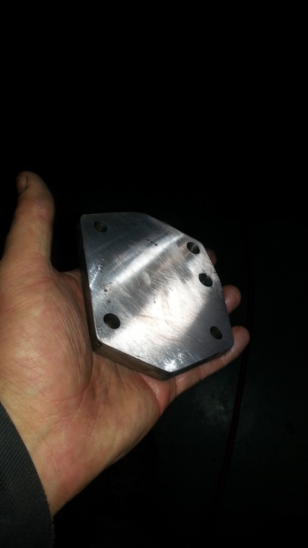
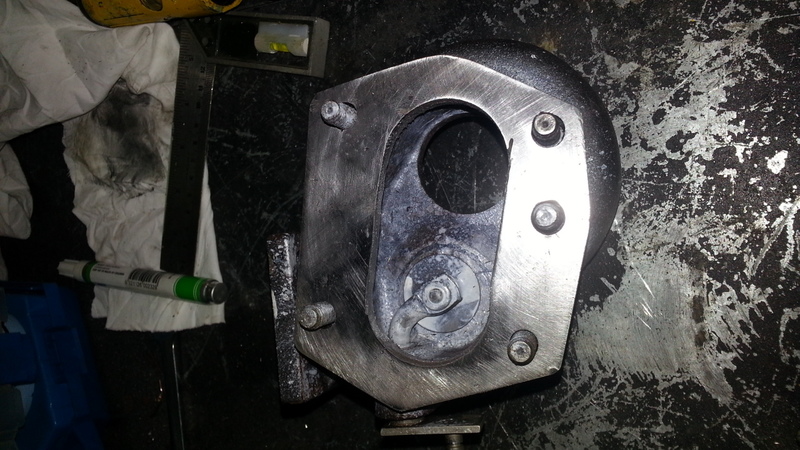
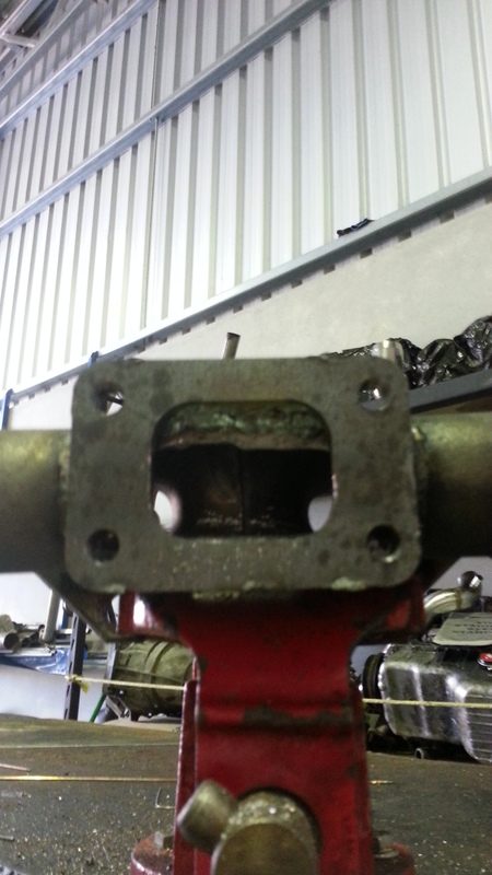
I have boxes of flanges but this one is a fraction different than a 25/28 one... Such is life.
And Ive been doing this too long to make mistakes like this :lol:
Ah well, whats half an hour out of my life? :P
Dann
And Ive been doing this too long to make mistakes like this :lol:
Ah well, whats half an hour out of my life? :P
Dann
Reply
1
1
07-23-2013, 11:10 AM
#47
Elite Member
Thread Starter
Join Date: Apr 2010
Location: Newcastle, Australia
Posts: 2,826
Total Cats: 67
]Big update time.
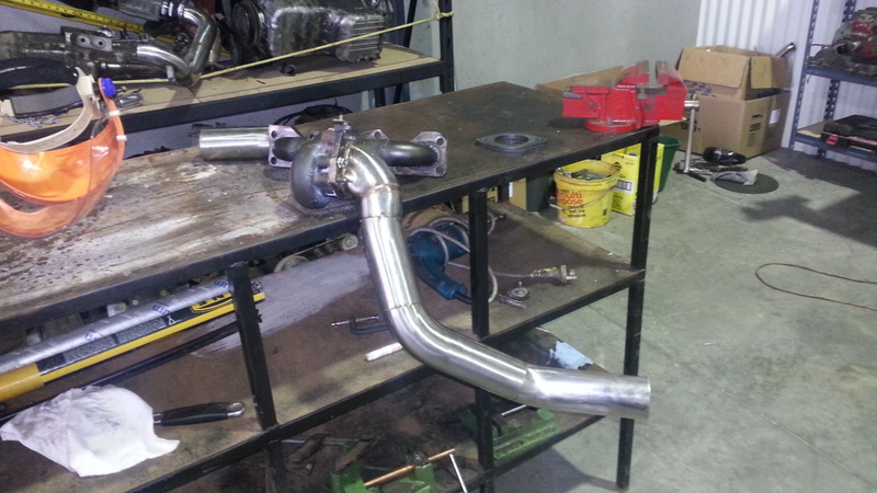
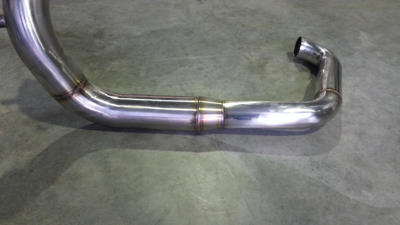
Tacked a couple of bends to the downpipe, this routing gives a LOT of clearance for working on the car.
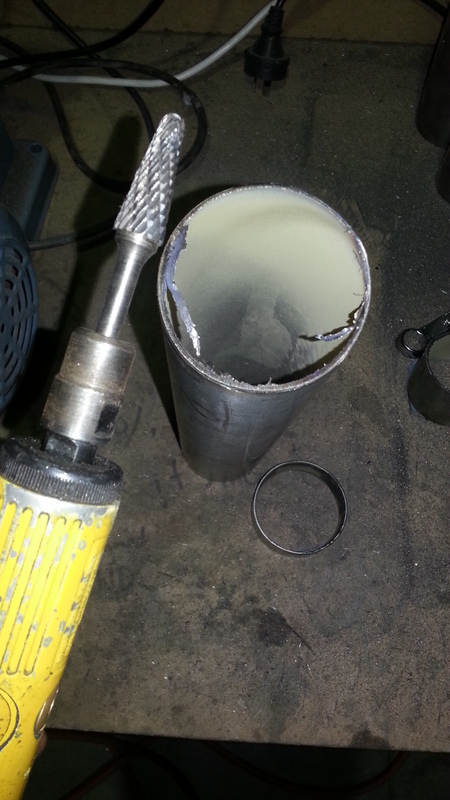
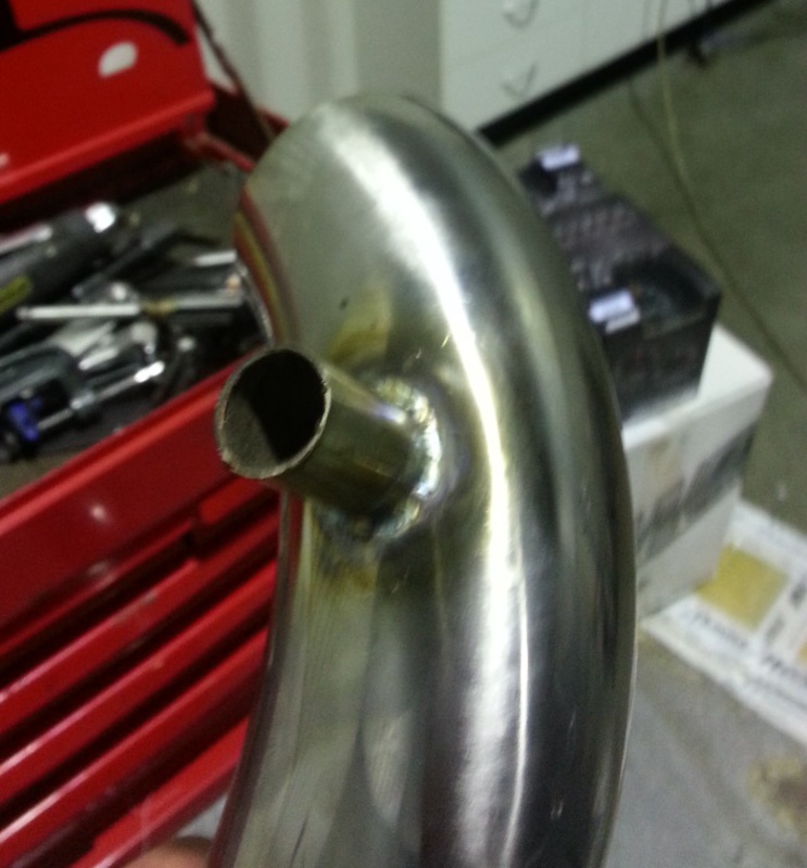
Here is a reducer cut in 2, this was 3>2. Now its a 3>2.5 and a 2.5>2.
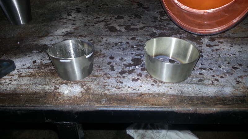
This demonstrates how it will work to bolt this to a stock 1.75" system, this car has a 2".
Nice flow.
Performance is all about the details, the die grinder is used a LOT when doing custom piping.
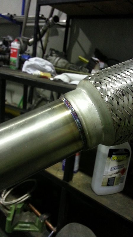
From top to bottom, 2" flange, 2>2.5" 316SS reducer, 2.5" SS straight, 2.5x6" SS flex pipe-double braid for flow.
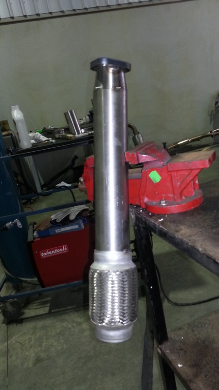
Tacked to the rest of the downpipe. This took 2 goes to get the flanges lining up to the millimetre.
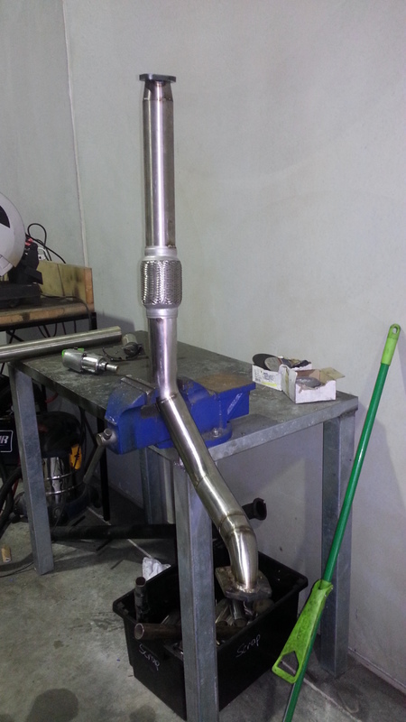
Nice straight path.
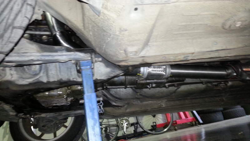
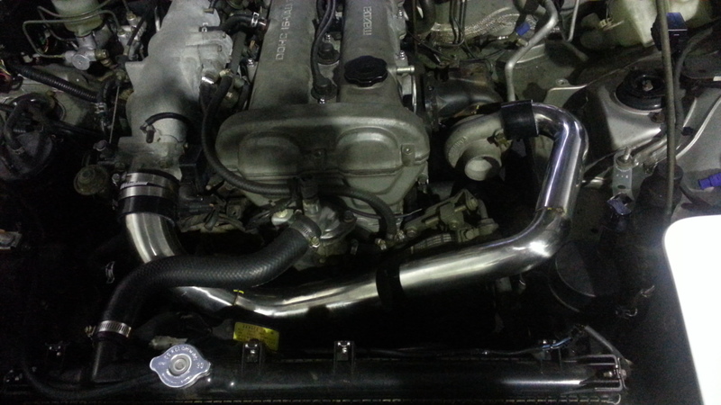
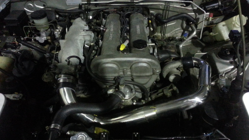
Installed, tucked up nice and high, 100% above the frame rails.
Getting started on the crossover pipe.
Path. Nice and short.
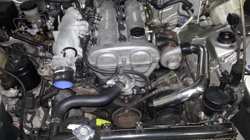
Throttle body side started.
How it all sits on the car, needs another 2.5>2" reducer and AIT bung for the MegaSquirt ecu, and the tube for the Idle Air Control (IAC valve).
Dann
Tacked a couple of bends to the downpipe, this routing gives a LOT of clearance for working on the car.
Here is a reducer cut in 2, this was 3>2. Now its a 3>2.5 and a 2.5>2.
This demonstrates how it will work to bolt this to a stock 1.75" system, this car has a 2".
Nice flow.
Performance is all about the details, the die grinder is used a LOT when doing custom piping.
From top to bottom, 2" flange, 2>2.5" 316SS reducer, 2.5" SS straight, 2.5x6" SS flex pipe-double braid for flow.
Tacked to the rest of the downpipe. This took 2 goes to get the flanges lining up to the millimetre.
Nice straight path.
Installed, tucked up nice and high, 100% above the frame rails.
Getting started on the crossover pipe.
Path. Nice and short.
Throttle body side started.
How it all sits on the car, needs another 2.5>2" reducer and AIT bung for the MegaSquirt ecu, and the tube for the Idle Air Control (IAC valve).
Dann
Reply
0
0
 07-23-2013, 11:13 AM
#51
Elite Member
Thread Starter
Join Date: Apr 2010
Location: Newcastle, Australia
Posts: 2,826
Total Cats: 67
Heres where we are up to, need an oil feed line, air filter, finish the pulse welds, drill the sump, bolt it together and clip the megasquirt in and tune 8)
This update is very pic heavy and helps explain SpeedFlow type fittings and their assembly.
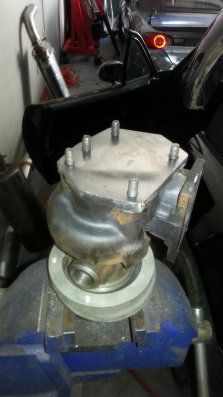
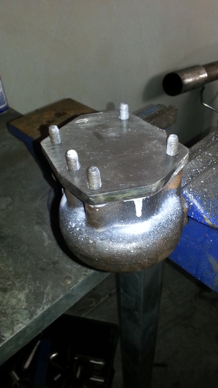
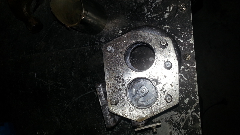
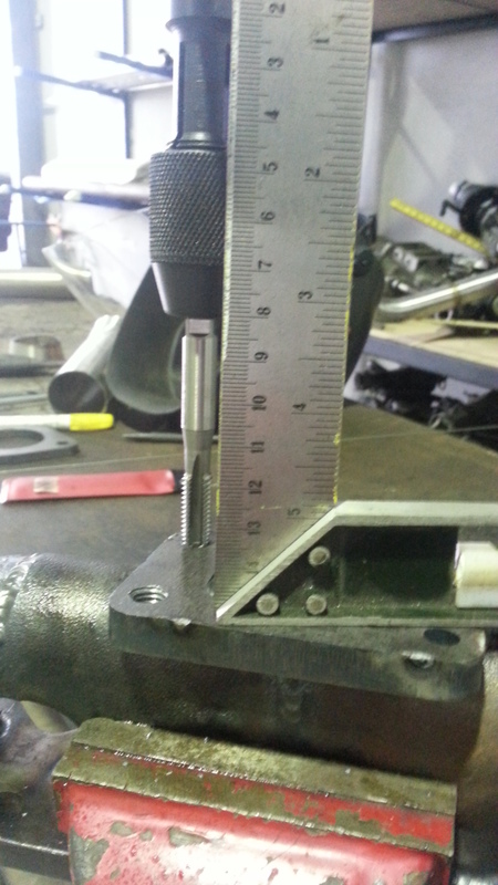
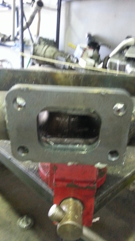
This flange, for some reason out of like 10 I purchased didnt come tapped, so a trip to the bolt shop and 20 bucks later its tapped.
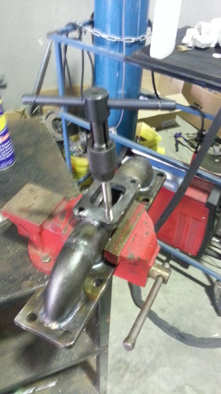
Use a square and eyeball the tap is vertical.
So here is the oil feed line, on a garrett this is a gas fitting, Ill feed this with a hardline from the head, any brake and clutch shop can make you this hardline for 30 bucks.
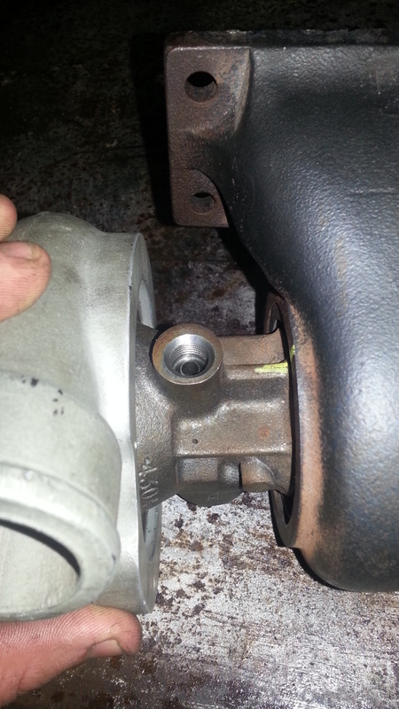
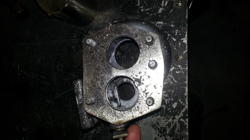
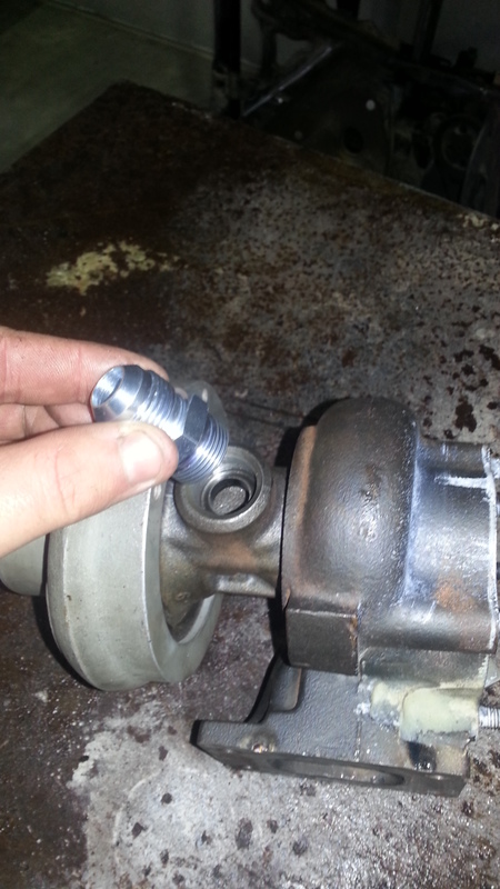
This is the oil return, much larger.
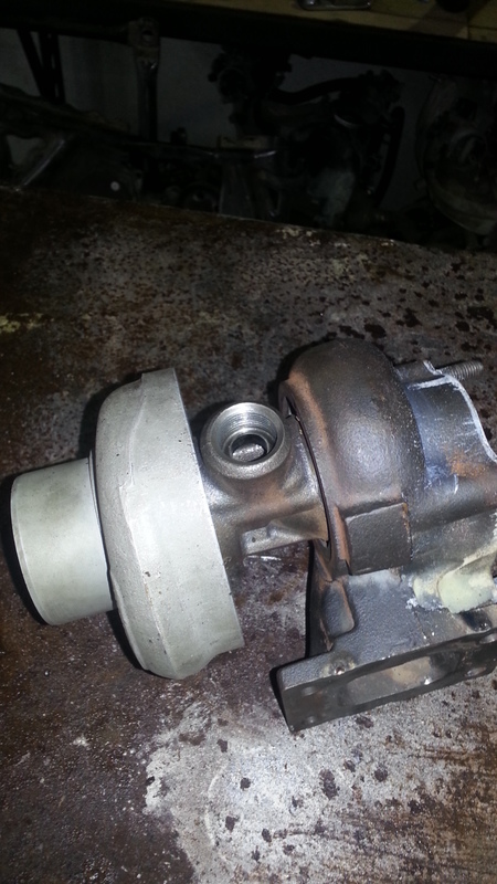
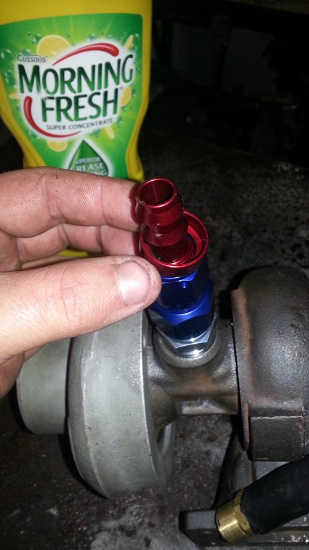
This particular turbo has an incredibly unusual fitting, Totally unavailable from SpeedFlow, 13 bucks later after a trip to an industrial hose shop I got a 22mmx1.5mm internal flare to -10JIC fitting, now back to the hotrod shop for a Speedflow adaptor and hosetail.
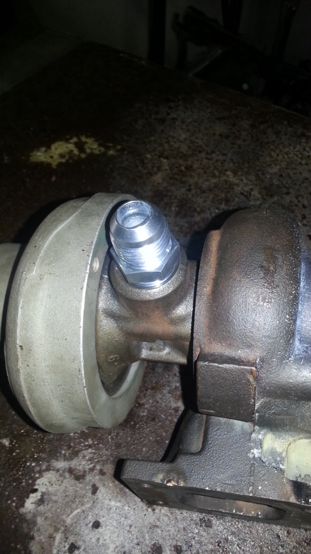
So with liquid threadtape, it gets screwed in. Use a spanner for final assembly.
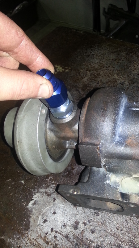
Then the JIC to -10 adaptor.
Then the -8 hose tail.
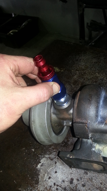
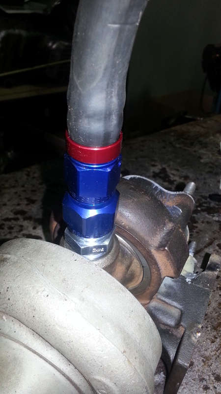
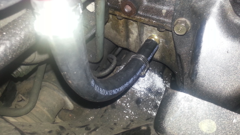
The hose gets pushed down hard like this to fit it on the barb. These barbs are high pressure and dont require a clamp, but I'm using one anyway.
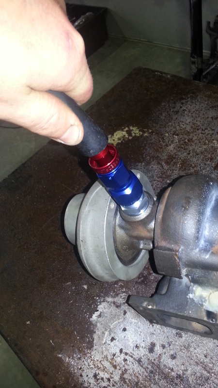
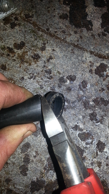
Cut a clean straight end from the hose, in this case we are using -10 heat resistant fire retardant efi capable hose.
Then into boiling water it goes to soften it.
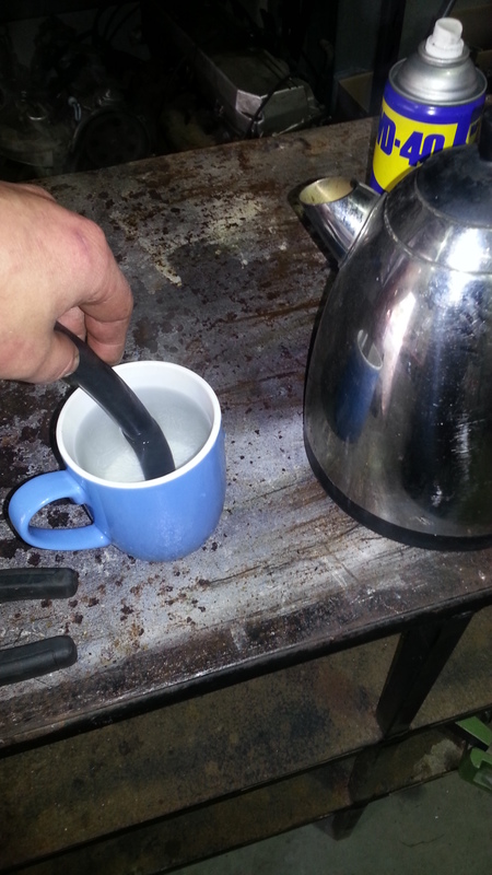
Some lubricant, use soap because it will dry up, unlike oil.
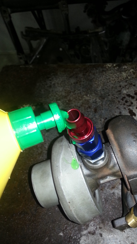
This collar must be on this direction before fitting the hose, this makes it look nice and tidy, THIS IS YOUR LAST CHANCE.
Push down HARD. In ONE motion. There are no second chances these barbs do not let go.
And a hose clamp because insurance is always recommended.
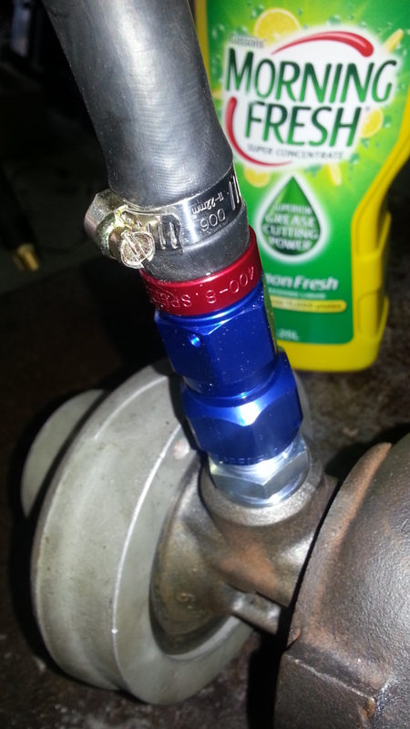
Not long now!
Dann
This update is very pic heavy and helps explain SpeedFlow type fittings and their assembly.
This flange, for some reason out of like 10 I purchased didnt come tapped, so a trip to the bolt shop and 20 bucks later its tapped.
Use a square and eyeball the tap is vertical.
So here is the oil feed line, on a garrett this is a gas fitting, Ill feed this with a hardline from the head, any brake and clutch shop can make you this hardline for 30 bucks.
This is the oil return, much larger.
This particular turbo has an incredibly unusual fitting, Totally unavailable from SpeedFlow, 13 bucks later after a trip to an industrial hose shop I got a 22mmx1.5mm internal flare to -10JIC fitting, now back to the hotrod shop for a Speedflow adaptor and hosetail.
So with liquid threadtape, it gets screwed in. Use a spanner for final assembly.
Then the JIC to -10 adaptor.
Then the -8 hose tail.
The hose gets pushed down hard like this to fit it on the barb. These barbs are high pressure and dont require a clamp, but I'm using one anyway.
Cut a clean straight end from the hose, in this case we are using -10 heat resistant fire retardant efi capable hose.
Then into boiling water it goes to soften it.
Some lubricant, use soap because it will dry up, unlike oil.
This collar must be on this direction before fitting the hose, this makes it look nice and tidy, THIS IS YOUR LAST CHANCE.
Push down HARD. In ONE motion. There are no second chances these barbs do not let go.
And a hose clamp because insurance is always recommended.
Not long now!
Dann
Last edited by nitrodann; 07-23-2013 at 11:44 AM.
Reply
0
0
07-23-2013, 11:14 AM
#52
Elite Member
Thread Starter
Join Date: Apr 2010
Location: Newcastle, Australia
Posts: 2,826
Total Cats: 67
Alright, here we go, the most fun part (not even slightly, and they dont get any better).
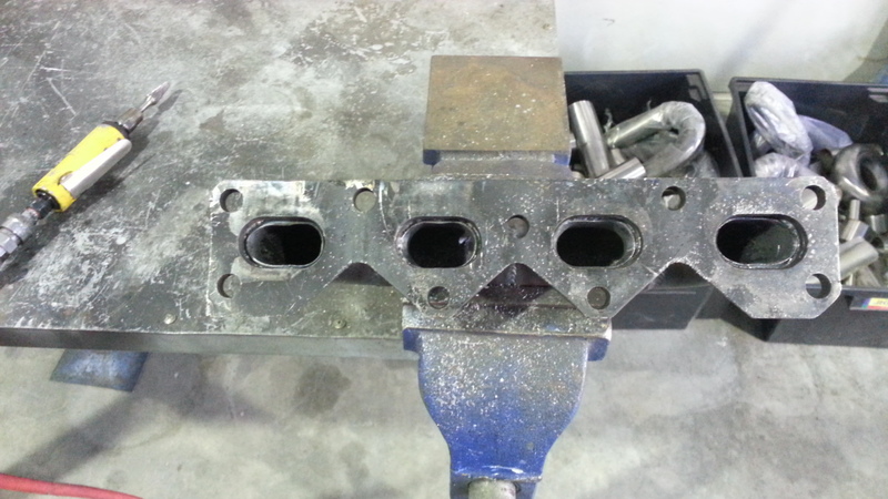
Drilling the sump and tapping it. And the first few are of my porting the manifold.
Here is the unported manifold. Horrible photo sorry.
Half ported.
Inlet ports getting done next.
Crossover pipe welded.
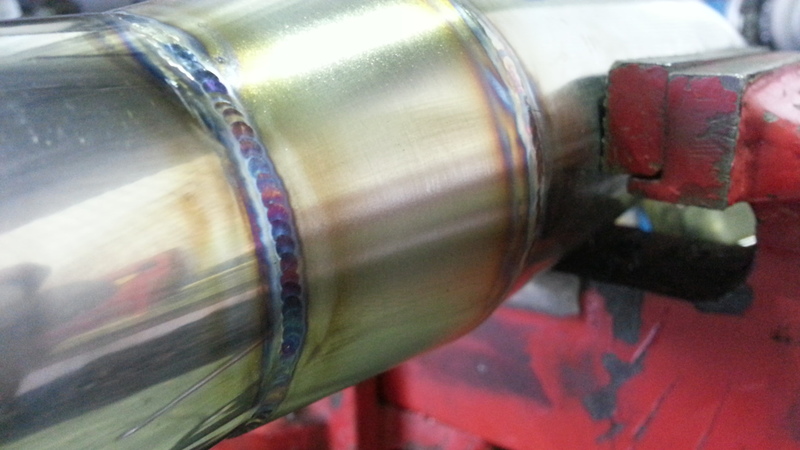
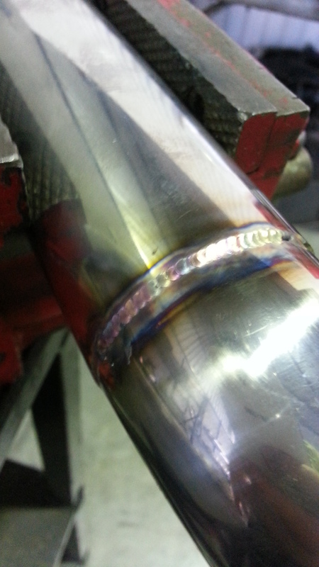
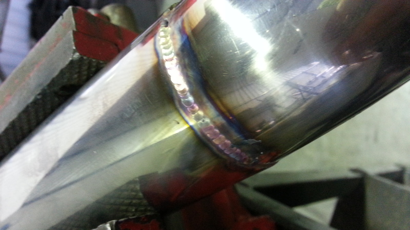
Downpipe welded. It has a double braid flex pipe for reliability.
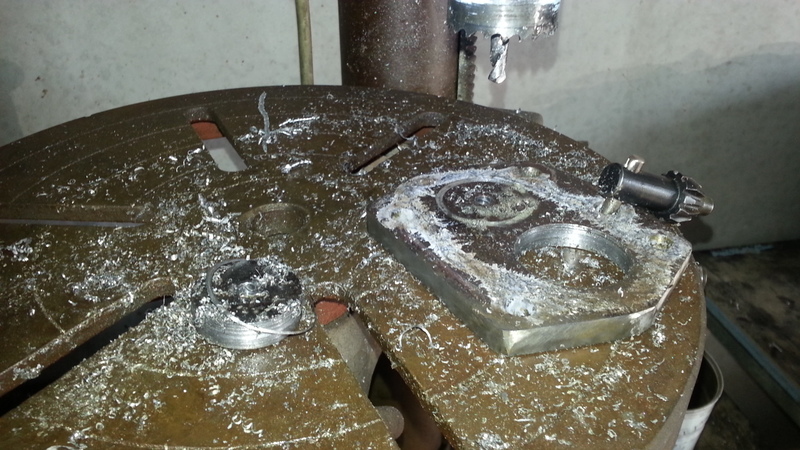
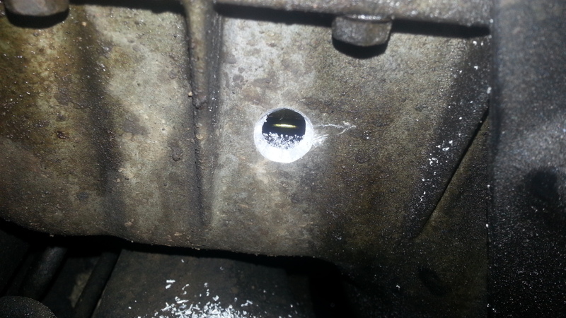
Drill a pilot hole for the oil return. This location is NOT the tradition (ie miataturbo wiki) location, the miataturbo location is suggested because its hard to hit the oil pickup pipe and puncture it from that location, Here im just using experience and care to ensure it doesnt happen, we will look and test for it later.
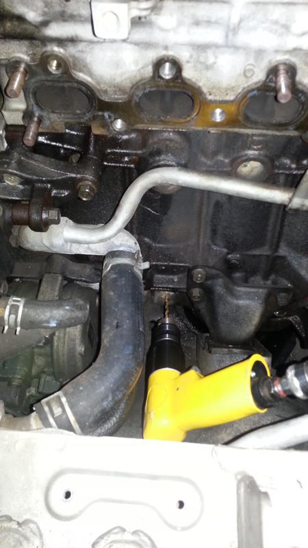
Hole has been drilled with a bit usually used to countersink screw heads, its called a countersinking bit. It eats the alloy like its nothing. You can see inside the hole the oil pickup running horizontally, its close here but Im being SUPER careful with depth.
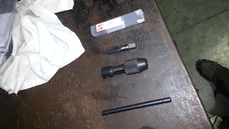
This is a 3/8 BSP tap and hand tapping piece, Ill be tapping with a ratchet not the hand tap (the 2 black bits, make a 'T').
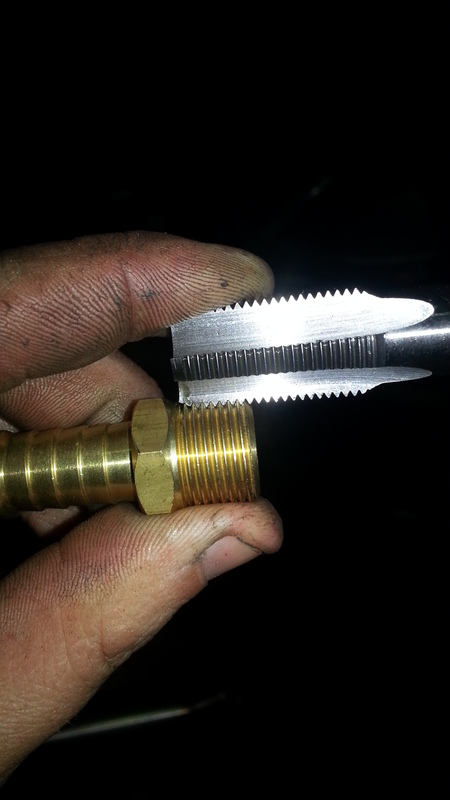
ALWAYS check the threads are the same by holding them in each other, this trick works for all bolts, you will know if its not right the threads simply wont seat.
Lets tap. Again being very careful to mark and check the depth.
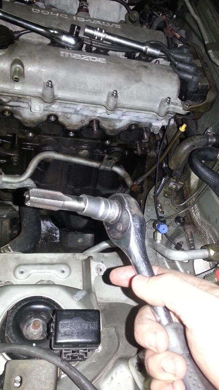
Awesome, we have return.
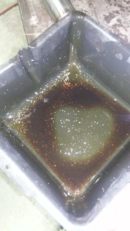
After flushing the sump with degreaser this came out, its very important to flush the sump after tapping.
So after I had done this I unclipped the injectors and ignition harness and hooked up a battery charger. I crank it and check that it makes oil pressure just off the key. It gets to 2 on the guage, this confirms the visual inspection that the oil pickup is not damaged. if you cut a hole in it the oil pump will suck air and you will not have pressure, this is why it must be tested with the starter motor.
Now Ill clean up the flange faces, add gasket maker, and bolt it together, with sealant on all of the threads.
I must add an oil feed, and clip in the megasquirt, and put my wideband on for a tune, then we go for a slow safe tune, making sure the mixture is very rich and taking it very easy on ignition timing, and see how the car goes.
Then its off to its owner over the weekend and he can enjoy it for a little while while he waits in line for a quick dyno touch up.
Dann
Drilling the sump and tapping it. And the first few are of my porting the manifold.
Here is the unported manifold. Horrible photo sorry.
Half ported.
Inlet ports getting done next.
Crossover pipe welded.
Downpipe welded. It has a double braid flex pipe for reliability.
Drill a pilot hole for the oil return. This location is NOT the tradition (ie miataturbo wiki) location, the miataturbo location is suggested because its hard to hit the oil pickup pipe and puncture it from that location, Here im just using experience and care to ensure it doesnt happen, we will look and test for it later.
Hole has been drilled with a bit usually used to countersink screw heads, its called a countersinking bit. It eats the alloy like its nothing. You can see inside the hole the oil pickup running horizontally, its close here but Im being SUPER careful with depth.
This is a 3/8 BSP tap and hand tapping piece, Ill be tapping with a ratchet not the hand tap (the 2 black bits, make a 'T').
ALWAYS check the threads are the same by holding them in each other, this trick works for all bolts, you will know if its not right the threads simply wont seat.
Lets tap. Again being very careful to mark and check the depth.
Awesome, we have return.
After flushing the sump with degreaser this came out, its very important to flush the sump after tapping.
So after I had done this I unclipped the injectors and ignition harness and hooked up a battery charger. I crank it and check that it makes oil pressure just off the key. It gets to 2 on the guage, this confirms the visual inspection that the oil pickup is not damaged. if you cut a hole in it the oil pump will suck air and you will not have pressure, this is why it must be tested with the starter motor.
Now Ill clean up the flange faces, add gasket maker, and bolt it together, with sealant on all of the threads.
I must add an oil feed, and clip in the megasquirt, and put my wideband on for a tune, then we go for a slow safe tune, making sure the mixture is very rich and taking it very easy on ignition timing, and see how the car goes.
Then its off to its owner over the weekend and he can enjoy it for a little while while he waits in line for a quick dyno touch up.
Dann
Reply
0
0
07-23-2013, 11:14 AM
#53
Elite Member
Thread Starter
Join Date: Apr 2010
Location: Newcastle, Australia
Posts: 2,826
Total Cats: 67
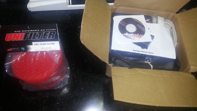
So this came in the mail, one from Gosford and one from the States.
This is 1000 bucks all up, the new Megasquirt PnP 2 for na6, an IAT bung and sensor, the cables and software, and the unifilter, which is much larger than I expected..
Dann
This is 1000 bucks all up, the new Megasquirt PnP 2 for na6, an IAT bung and sensor, the cables and software, and the unifilter, which is much larger than I expected..
Dann
Reply
0
0
 07-23-2013, 11:29 AM
#56
Elite Member
Thread Starter
Join Date: Apr 2010
Location: Newcastle, Australia
Posts: 2,826
Total Cats: 67
Fittings confuse me, metric to imperial and back again is a real headfuck for me, especially with AN and JIC and adaptors with codenames you have to remember, but Im certain that the adaptor is necessary.
Dan
Dan
Reply
0
0
07-23-2013, 11:35 AM
#58
Elite Member
Thread Starter
Join Date: Apr 2010
Location: Newcastle, Australia
Posts: 2,826
Total Cats: 67
Yeah but I dont think it has -10 hose, it has -8 hose, so it has the adaptor first.
I just gave the fitting I got, and the hose I needed to the hotrod shop and purchased the SpeedFlow fittings.
Dann
I just gave the fitting I got, and the hose I needed to the hotrod shop and purchased the SpeedFlow fittings.
Dann
Reply
0
0


