
ABSURDflow Turbo KLDE Mazda V6 Thread

 05-21-2012, 08:34 AM
#282
Elite Member

Thread Starter
iTrader: (9)
Join Date: Jun 2006
Location: Chesterfield, NJ
Posts: 6,930
Total Cats: 404

FM Frame rails with plates welded to them. Piece of straight mild steel rect. tubing bolts to the frame rail plates. Another plate in the center has the holes for the trans mount (mustang/energy suspension polyurethane). Also there is a plate added after the fact to bolt to one of the front PPF bolt holes. I could have made the trans mount & PPF mount all one plate but the PPF location was done much later than the trans mount.
There's lots of room for a 3" pipe above the cross member. I may be able to use my old exhaust as-is. I am not sure if I should gut my metal core cat or not.
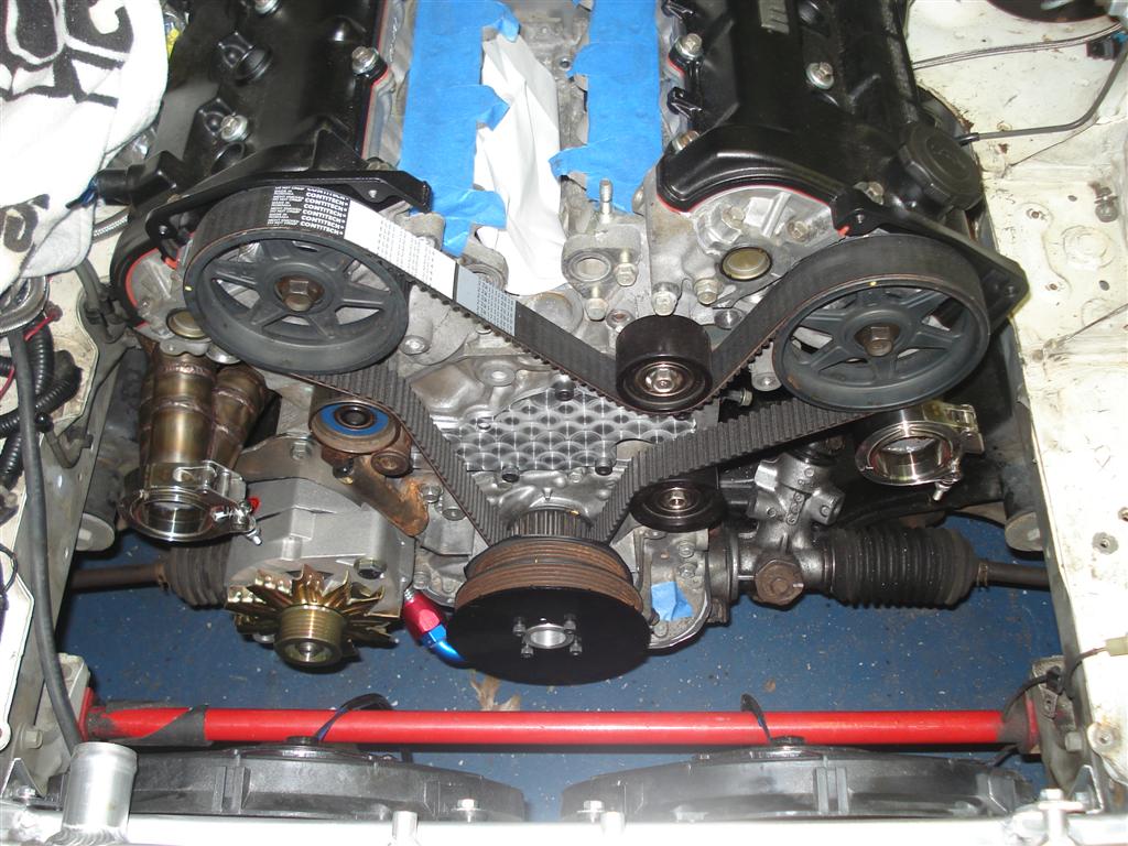
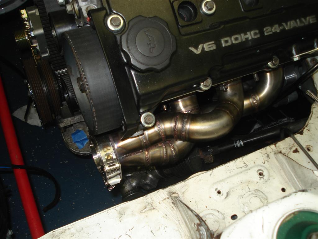
Hopefully there's ample room for the turbo stuffs up there. It seems like the engine is further back than the other KL swaps going on that use the miata transmission. I pushed the engine back until the pass. cyl. head hit the rear shelf but then I ended up hacksawing the interfering EGR? boss off so there is actually probably another half inch or more I can move it back, too late for that though.

Reply
 0
0

0

 05-21-2012, 09:03 AM
#285
Elite Member
Thread Starter
iTrader: (9)
Join Date: Jun 2006
Location: Chesterfield, NJ
Posts: 6,930
Total Cats: 404
Buy it! I'll make you a package deal. Be a big boy and go 1.8.
The new V6 intake mani will be just as square.
I hope so! I am pretty sure I tightened those windage screen screws... I have a good 1/4" minimum clearance around the oil pan/subframe after hammering the tight spots.
The new V6 intake mani will be just as square.
I have a good 1/4" minimum clearance around the oil pan/subframe after hammering the tight spots.
Reply
0
0
 05-21-2012, 10:33 AM
#287
Elite Member
Thread Starter
iTrader: (9)
Join Date: Jun 2006
Location: Chesterfield, NJ
Posts: 6,930
Total Cats: 404
Thanks. I was considering the heim-joint style gizmo earlier, but when I threw the PPF in there and it basically lined up perfectly the choice was simple. It could have been used as-is with no modification at all if using an OEM sized driveshaft & yolks. The front yolk on my 3" driveshaft interfered with the top part of the PPF so I Faefloral'ed it off.
Reply
0
0
 05-21-2012, 12:27 PM
#289

I like your shifter doo-hickie. A couple of my buddies put a T45 in a 4.6L Thunderbird, which required a similar shifter relocation, but they built a second shifter box behind the first one and ran a shift shaft extension through the freeze plug in the back of the original shifter box. It was a much less elegant solution than yours.
Reply
0
0
 05-29-2012, 10:21 PM
#291
Elite Member
Thread Starter
iTrader: (9)
Join Date: Jun 2006
Location: Chesterfield, NJ
Posts: 6,930
Total Cats: 404
Thanks POOFS, first post eh. 
Manifolds finally done after going thru 4 pairs of Vibrant vband flanges in order to find a set that are the "made in usa" ones that are designed correctly. The foreign ones (per the label) are designed to slip inside of 2" pipe, so the ID is a good .125" smaller. Dumb. Anyway, "Y" collector pipe next. Slow going, weekends are busy doing other fun things! Plus welding in 90�F garage is no fun.
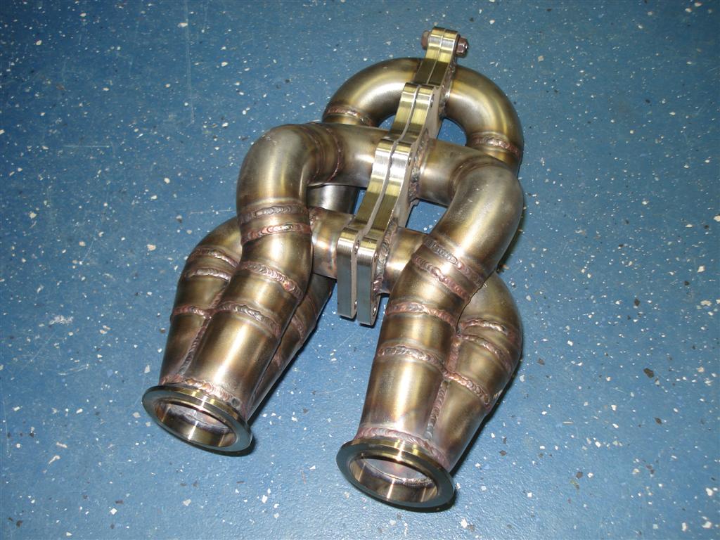
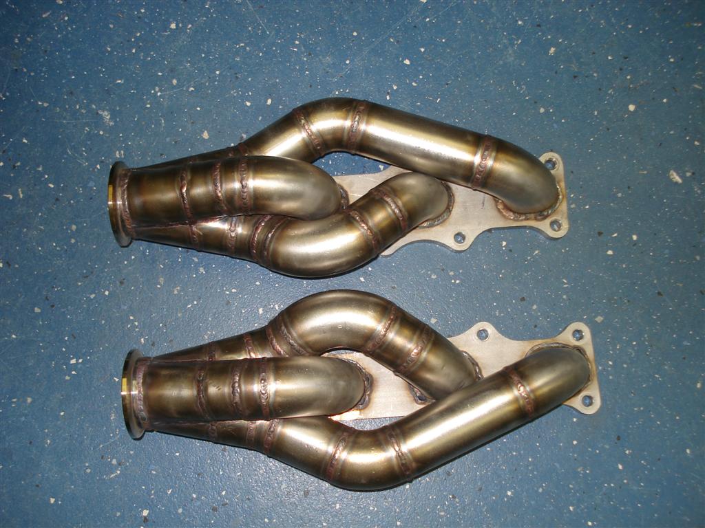
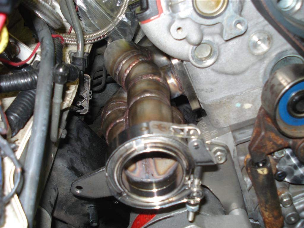
Manifolds finally done after going thru 4 pairs of Vibrant vband flanges in order to find a set that are the "made in usa" ones that are designed correctly. The foreign ones (per the label) are designed to slip inside of 2" pipe, so the ID is a good .125" smaller. Dumb. Anyway, "Y" collector pipe next. Slow going, weekends are busy doing other fun things! Plus welding in 90�F garage is no fun.
Reply
2
2


 06-01-2012, 11:49 PM
#296
Elite Member
Thread Starter
iTrader: (9)
Join Date: Jun 2006
Location: Chesterfield, NJ
Posts: 6,930
Total Cats: 404
Huh? I didn't do anything to the oil pump. I do still have to plug the original dipstick hole, hence the blue tape. I'll still probably forget about it.
If you meant the waterpump plate, I attempted to machine turn it with a wooden dowel and some valve lapping powder at lunch one day. Didn't turn out so good. I may spraypaint it black again, easy to do, it's O-ringed so don't have to worry about cleaning/reapplying silicone.
Thanks!
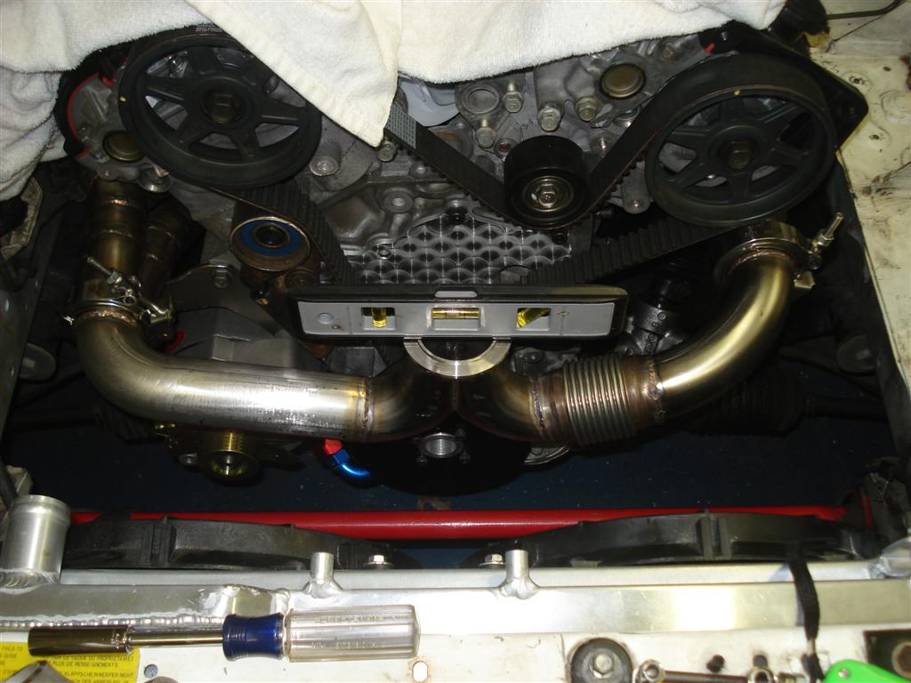
Haha I have my mockup 2560 and the churbo 2871 lying around, they would fit but it would be more difficult to plumb them. The Y pipe below only took me 8 hours, I can't imagine how long doing two turbos would take. I'm sslllloooowwwwww.
FEED ME!
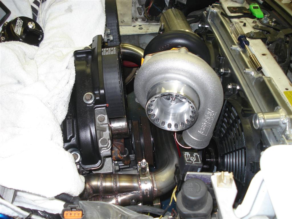
I could probably run an OE style radiator and the original fans if I went with the T04B compressor housing. Oh well.
I like this one, shows off the header better.

I guess I should wire the bitch up. Ugh. I still have to learn me some Arduino too. FML.
If you meant the waterpump plate, I attempted to machine turn it with a wooden dowel and some valve lapping powder at lunch one day. Didn't turn out so good. I may spraypaint it black again, easy to do, it's O-ringed so don't have to worry about cleaning/reapplying silicone.
Thanks!
FEED ME!
I could probably run an OE style radiator and the original fans if I went with the T04B compressor housing. Oh well.
I like this one, shows off the header better.
I guess I should wire the bitch up. Ugh. I still have to learn me some Arduino too. FML.
Last edited by TurboTim; 06-02-2012 at 12:02 AM.
Reply
0
0
06-02-2012, 07:42 AM
#298
Cpt. Slow
iTrader: (25)
Join Date: Oct 2005
Location: Oregon City, OR
Posts: 14,429
Total Cats: 1,207
I liked it when I still thought I'd see two turbos, downpipes facing each other, with filters behind each headlight. The symmetry between the filters, downpipes, drains, and feeds would have been awesome, with the only Y pipe being the one going into the engine.
But whatever, I'm sure this will "work".
But whatever, I'm sure this will "work".
Reply
0
0


