
94 MSPNP SR20 DIY Build
 08-27-2007, 12:28 AM
#1
Junior Member
Thread Starter

Join Date: May 2007
Location: Mountain View, CA
Posts: 220
Total Cats: 0
Here it goes:
All of the pics are at: http://s243.photobucket.com/albums/ff276/kylelind/
I wanted to share and be shared with on all that I am going to do to my car, so I am going to try my best to keep this thread up to date and helpful for all. I bought the car as a spec miata setup with all of the suspension and safety stuff done, so I am tackling the engine part of the beast. I am trying to do it all myself and make it nice, we will see how that goes....
I bought a SR20 turbo from a smog shop for $50 that had a broken stud in the exhaust flange. I rebuilt it and removed the stud (nasty job) and now it seems to be a quality unit. My plan is to do a v-mount intercooler setup without chopping up the braces in the front. I bought a china cooler and chopped it up to fit the space. Now it is welded back together and ready to go. I am going with a Greddy type-s BOV and will eventually recirculate. I am only planning on 200-210whp so hopefully I wont jack up the engine.
Speaking of jacked engine I checked my compression with a Harbor Freight guage and it said I had 125 on all 4?? Either the guage is bad and they are all even-steven, or my engine is crap. Would I even have good power at that compression level?
Also if you can help me with the MSPNP I posted in that section with a misfiring problem.
So, I will keep ya'll updated on my progress and check out the pictures and list of parts that I ordered on photobucket. Also if anyone lives in the bay area and wants to come play let me know.

Reply
 0
0

0
08-27-2007, 12:47 AM
#2
When you checked out compression did you hold the throttle to the floor?
Also, when checking your compression you need to pull the fuse for your fuel and disconnect the harness from your coils because constant cranking with no spark plug in the wires will burn them up.
Also, when checking your compression you need to pull the fuse for your fuel and disconnect the harness from your coils because constant cranking with no spark plug in the wires will burn them up.
Reply
0
0
08-27-2007, 02:23 AM
#5
Former Vendor

iTrader: (31)

Join Date: Nov 2006
Location: Sunnyvale, CA
Posts: 15,442
Total Cats: 2,104
Closed throttle = gauge is limited by amount of air in the intake manifold with the TB closed
Open throttle = gauge limited by the seals the rings and valves make
Fuel fuse out so you don't flood the motor
coil disconnected because you can burn the coil up by cranking the motor over with the coil un-grounded (usually it grounds via the spark plugs)
Did the other USB-Serial adaptor work out?
Open throttle = gauge limited by the seals the rings and valves make
Fuel fuse out so you don't flood the motor
coil disconnected because you can burn the coil up by cranking the motor over with the coil un-grounded (usually it grounds via the spark plugs)
Did the other USB-Serial adaptor work out?
Reply
0
0
08-27-2007, 09:13 PM
#9
Junior Member
Thread Starter
Join Date: May 2007
Location: Mountain View, CA
Posts: 220
Total Cats: 0
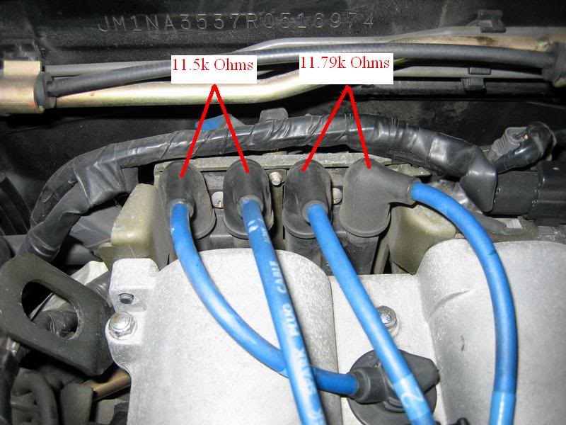
Here are the resistance numbers for the two coils. This image shows the locations where I took the values:
<a href="http://photobucket.com" target="_blank"><img src="http://i243.photobucket.com/albums/ff276/kylelind/IMG_1511.jpg" border="0" alt="Photo Sharing and Video Hosting at Photobucket"></a>
Just in case the photo does not open, the passenger side was 11.5k Ohms between the teo plugs and driver was 11.79k Ohms.
What does this mean?? What range should they be in? Thanks!
Reply
0
0
 08-28-2007, 10:22 PM
#12
I just got the same turbo in the mail, and I was just about to make thread to ask this but instead maybe you can help.
1. How exactly do I adjust the boost on it? It doesn't have a threaded waste gate actuator rod. How much boost is it set for with the waste gate actuator on it?
2. How do I clock it so the output of the compressor is pointing downward? It doesn't seem to be possible because of the waste gate actuator and bracket, but its no biggie, just curious how others do it.
3. How do I clock the compressor a bit because the rod that comes out of the wastegate actuator isnt attached to the arm on the turbine housing? I see some sort of metal ring that goes around it on the CHRA side and i'm guessing if I compress that it will turn?
4. Is it normal for the flap for the waste gate to be a bit loose? I can only guess it stiffens with thermal expansion.
Your pretty lucky that you got the inlet adapter as well, I only got the outlet.
Thanks in advance.
Last edited by Saml01; 08-28-2007 at 11:43 PM.
Reply
0
0
08-29-2007, 12:25 AM
#13
Junior Member
Thread Starter
Join Date: May 2007
Location: Mountain View, CA
Posts: 220
Total Cats: 0
1. To adjust the boost you need a boost controller of some sort. Manual or electronic, which can be home made (see sticky in DIY thread). The rod only sets the pre-tension of the wastegate.
2. You would need to make your own bracket, I am keeping mine in the stock orientation.
3. Yeah, there is a burly snap-ring that holds the compressor in place. You may be able to muscle it around but will probroably have to remove the snap ring.
4. The wastegate should press closed tightly with the actuator connected, but will be loose when open.
Good Luck!
Reply
0
0
08-29-2007, 12:27 AM
#14
Junior Member
Thread Starter
Join Date: May 2007
Location: Mountain View, CA
Posts: 220
Total Cats: 0
Back to my compression check, holding the throttle open did produce 183psi instead of 125....much better. I am still not sure if the resistance values for my coils are any good. Can someone help me out? Here they are.
Reply
0
0
08-29-2007, 12:27 AM
#15
Some people get away with using a wood handle(broom) in the compressor outlet to clock their turbos. Only works if your snap ring isn't rusted onlike a MF.
Those coil values look good to me. But you might want to look around some more. I think the specs are between 8-12 ohms and yours are right up in the top margin and close together.
Those coil values look good to me. But you might want to look around some more. I think the specs are between 8-12 ohms and yours are right up in the top margin and close together.
Reply
0
0
08-29-2007, 12:48 AM
#16
Junior Member
Thread Starter
Join Date: May 2007
Location: Mountain View, CA
Posts: 220
Total Cats: 0
Here is a bunch of new toys that I got today, tubing from acestainless.com that looks like very good quality, and a bunch of stuff from summit including a new 3" aluminum radiator for the v-mount, also good looking. STOKED!!


Reply
0
0
08-29-2007, 12:53 AM
#17
Junior Member
Thread Starter
Join Date: May 2007
Location: Mountain View, CA
Posts: 220
Total Cats: 0
I will also be testing out the ebay F1 stage 3 clutch so I will keep everyone posted on that item. Another one of interest is the exhaust band clamp that I intend to use instead of bolt flanges. It looks pretty nice and I am going to incorporate some springs in to hold the butt-joint together better. It is very cheap and easy though. $9 for the clamp, $2 for springs, and just cut pipes butted together. We will see....
Reply
0
0
08-29-2007, 12:58 AM
#18
Never seen someone use the donut they sell for exhaust work.
Next time when shopping for tubing check out racing-solutions.com (google maybe) they offer a discount to homemadeturbo.com members as well. Ace is just fine of course, they have good quality stuff, so i'm told.
Next time when shopping for tubing check out racing-solutions.com (google maybe) they offer a discount to homemadeturbo.com members as well. Ace is just fine of course, they have good quality stuff, so i'm told.
Reply
0
0
08-29-2007, 01:14 AM
#20
Its my first turbo so im a bit OCD'ish.
Thanks again, good luck with your build. I will be watching this thread very closely.
Reply
0
0


