Something more Imaginative?
 09-06-2010, 11:43 PM
#1
Senior Member

Thread Starter
iTrader: (3)

Join Date: May 2005
Location: Mass.
Posts: 811
Total Cats: 43
I finally am started to gain focus on my rebuild so I figured at kick off a build thread.
I 'bought' the car from my father at age 15 when he acknowledged the proposed spec miata build was not likely. I decided to hop on the tuner bandwagon and turbo it at 17. The car then saw a minor rebuild at 18, but college, beer, and hipster single-speeds caused my mind to wander. The car , as a result, ended up sitting in my parents garage for the past 6 years. Nostalgia has set in prematurely and I've decided to get it back on the road.
The first build, circa 2002:

The first rebuild (after I grew some taste), circa 2003:


Now, on to the current progress. Ironically, everything in the build is changing except (amazingly) the Greddy manifold. Stupid? Perhaps, but the manifold has barely moved (less than .01" over 6K) and I didn't realize that my turbo **** the bed until after I had ARTech fab a DP and exhaust ... oh well.
Cue the **** phone pics

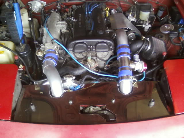
Engine bay, as it sit. The plan is to run the IC pipes over the radiator ... the path should be very short. Though I'm not convinced the Carbing brace is the god-like product it's made out to be, one cannot deny the quality of the welds and how pisser is looks in the bay.

This shot shows a couple bits I've completely thus far. Smoothed Auto TB, M-Tuned rail, hard line fuel feed, water jetted IAC blocking plates:

I'm using a 30 degree elbow to quick the intake tract back up and over the Koyo rad:


Close up of the M-tuned fuel rail. I used Earls hard coated fittings and tube nuts with an Aeromotive 5/16 nipple adapter to connect to the oem lines:

A shot of the radiator brackets to create clearance for the IC pipes. They're designed to keep to base of the radiator in a near OEM location to provide plenty of sway bar clearance - this simply tilts to radiator back

I found a direct bolt in for the Greddy manifold on ebay. The vendor was nice enough to check the flange rubs I e-mailed him. He said it came with a VR4 'upgrade'. All I know is it's a mitsu turbo, the flanges bolt up, and yes ... it's water cooled.

A comparison. I'll be swapping over my polished Greddy housing and fabricating a WG bracket for my Forge WG. I've heard good and bad about the Forge WG, but it's adjustable, rebuild-able, looks pretty and I got it for next to nothing:

I started mocking up my new AEM gauges. I decided to keep the gauges up high ... a little more work but worth it IMO:

The finished product. 10mm delrin, 2 3/8" and 2 1/16" forstner bits, a bridgeport, an hour of polishing = profit. I'll be using my AC button as my hazards switch:

They're angled at around 9 deg which provides a very clear few of the gauges at a glance:

Mild panic at first sight of box ... all well inside:

Beauty. ARTech goodies:

I've got a lot of work ahead, hopefully pace will pick up come this fall and winter. I've got a MSPNP to install and tune, a mild wire tuck to complete, an m-tuned reroute to install, and some general maintenance.
Hopefully by next summer the 1.6 diff will be gone and the car will be sitting an a proper suspension and not 70k blown oem shocks.
-Zach
I 'bought' the car from my father at age 15 when he acknowledged the proposed spec miata build was not likely. I decided to hop on the tuner bandwagon and turbo it at 17. The car then saw a minor rebuild at 18, but college, beer, and hipster single-speeds caused my mind to wander. The car , as a result, ended up sitting in my parents garage for the past 6 years. Nostalgia has set in prematurely and I've decided to get it back on the road.
The first build, circa 2002:
The first rebuild (after I grew some taste), circa 2003:
Now, on to the current progress. Ironically, everything in the build is changing except (amazingly) the Greddy manifold. Stupid? Perhaps, but the manifold has barely moved (less than .01" over 6K) and I didn't realize that my turbo **** the bed until after I had ARTech fab a DP and exhaust ... oh well.
Cue the **** phone pics
Engine bay, as it sit. The plan is to run the IC pipes over the radiator ... the path should be very short. Though I'm not convinced the Carbing brace is the god-like product it's made out to be, one cannot deny the quality of the welds and how pisser is looks in the bay.
This shot shows a couple bits I've completely thus far. Smoothed Auto TB, M-Tuned rail, hard line fuel feed, water jetted IAC blocking plates:
I'm using a 30 degree elbow to quick the intake tract back up and over the Koyo rad:
Close up of the M-tuned fuel rail. I used Earls hard coated fittings and tube nuts with an Aeromotive 5/16 nipple adapter to connect to the oem lines:
A shot of the radiator brackets to create clearance for the IC pipes. They're designed to keep to base of the radiator in a near OEM location to provide plenty of sway bar clearance - this simply tilts to radiator back
I found a direct bolt in for the Greddy manifold on ebay. The vendor was nice enough to check the flange rubs I e-mailed him. He said it came with a VR4 'upgrade'. All I know is it's a mitsu turbo, the flanges bolt up, and yes ... it's water cooled.
A comparison. I'll be swapping over my polished Greddy housing and fabricating a WG bracket for my Forge WG. I've heard good and bad about the Forge WG, but it's adjustable, rebuild-able, looks pretty and I got it for next to nothing:
I started mocking up my new AEM gauges. I decided to keep the gauges up high ... a little more work but worth it IMO:
The finished product. 10mm delrin, 2 3/8" and 2 1/16" forstner bits, a bridgeport, an hour of polishing = profit. I'll be using my AC button as my hazards switch:
They're angled at around 9 deg which provides a very clear few of the gauges at a glance:
Mild panic at first sight of box ... all well inside:
Beauty. ARTech goodies:
I've got a lot of work ahead, hopefully pace will pick up come this fall and winter. I've got a MSPNP to install and tune, a mild wire tuck to complete, an m-tuned reroute to install, and some general maintenance.
Hopefully by next summer the 1.6 diff will be gone and the car will be sitting an a proper suspension and not 70k blown oem shocks.
-Zach

Reply
 0
0

0

 09-07-2010, 09:04 AM
#5
Senior Member
Thread Starter
iTrader: (3)
Join Date: May 2005
Location: Mass.
Posts: 811
Total Cats: 43
-Zach
Reply
0
0
09-07-2010, 09:16 AM
#6
Senior Member
Thread Starter
iTrader: (3)
Join Date: May 2005
Location: Mass.
Posts: 811
Total Cats: 43
Also, the car is garaged a good hour from work and 40 minutes from my apartment so must of the work gets done piece by piece ... gauge console at work, throttle body and fuel rail at the apartment, etc. It let's me focus on each task and prevents me from becoming to anxious and just throwing the thing together. It also gives me time to think things over ... I've made a couple alterations to the plan for the better because of this.
-Zach
Reply
0
0

 09-07-2010, 08:41 PM
#8
Senior Member
Thread Starter
iTrader: (3)
Join Date: May 2005
Location: Mass.
Posts: 811
Total Cats: 43
more AN fittings came today so I can make some more progress in that area. The plan is to run a set up similar to BEGI with braided lines from the block to a bracket mounted to the valve cover and then hard lines from there to the turbo.
I drilled and tapped the manifold for 10 mm studs tonight on the Bridgeport, however, we work at a pretty small scale (in terms of machining needs) at my company so I wasn't able to surface the flanges. I need to source I local shop to do this and then I can ship the parts out for c-coat and started bolting this thing back together.
The thread will be slow for the rest of the month as I'll be overseas for a bit enjoying my GF's company paid hotel room in Paris, but once I get back I plan to hit the car hard.
-Zach
Reply
0
0

 11-07-2010, 12:11 AM
#10
Senior Member
Thread Starter
iTrader: (3)
Join Date: May 2005
Location: Mass.
Posts: 811
Total Cats: 43
minor update.
I've finished machining the intercooler bracket out of some .25" aluminum and had the some new couplers and the wastegate signal/IAT bungs welded onto the intercooler.
The IAT sensor is located at the very end of the intercooler path and since the distance of the cold side piping is very short (<20") and ALL silicon (meaning it's well insulated) I'm not too concerned.
I've got my DIYAUTO electric boost controller so I'm making a bracket for that.
The big debate now is whether I go VTA or recirculate. I prefer recirc simply because it's less obnoxious however, like budget racers image I have very little room on the cold side so it needs to go on the cold side of the intercooler or on the hot side. Decisions.
One question for the MS folk. I need a signal line for my AEM boost sensor and I was planning on mounting it next to my MSPNP and splitting the signal line to the MS. It keeps the line short and the sensor in a nice protected area - bad idea?
Photo updates soon.
-Zach
Reply
0
0
11-07-2010, 01:44 AM
#11
Boost Pope

iTrader: (8)
Join Date: Sep 2005
Location: Chicago. (The less-murder part.)
Posts: 33,339
Total Cats: 6,793
Very nice work on the gauge mounting. I don't think I've ever seen such a setup that was so cleanly DIYed.
[QUOTE=thasac;653796]I prefer recirc simply because it's less obnoxious however, like budget racers image I have very little room on the cold side so it needs to go on the cold side of the intercooler or on the hot side.[quote]If you have a loosely-sprung valve (such as a Greddy RS-style with the inner spring removed) and place an air filter on the exhaust, it's not terribly loud at all. A bit of a slight "whoosh" but nothing attention-grabbing.
Shouldn't be a problem. Since there is virtually zero flow through the line going to a boost gauge or MAP sensor, there will be essentially zero pressure drop across it. Thus, you can hang as many devices off of the line as you wish. I have one line going through the firewall which is teed off to three things- a mechanical boost/vac gauge, the MAP sensor for the WI system, and the MegaSquirt MAP sensor.
[QUOTE=thasac;653796]I prefer recirc simply because it's less obnoxious however, like budget racers image I have very little room on the cold side so it needs to go on the cold side of the intercooler or on the hot side.[quote]If you have a loosely-sprung valve (such as a Greddy RS-style with the inner spring removed) and place an air filter on the exhaust, it's not terribly loud at all. A bit of a slight "whoosh" but nothing attention-grabbing.
One question for the MS folk. I need a signal line for my AEM boost sensor and I was planning on mounting it next to my MSPNP and splitting the signal line to the MS. It keeps the line short and the sensor in a nice protected area - bad idea?
Reply
0
0
11-07-2010, 09:02 AM
#12
Senior Member
Thread Starter
iTrader: (3)
Join Date: May 2005
Location: Mass.
Posts: 811
Total Cats: 43
[QUOTE=Joe Perez;653820]Very nice work on the gauge mounting. I don't think I've ever seen such a setup that was so cleanly DIYed.
[QUOTE=thasac;653796]I prefer recirc simply because it's less obnoxious however, like budget racers image I have very little room on the cold side so it needs to go on the cold side of the intercooler or on the hot side.
Thanks for the reply Joe.
I was leaning towards a VTA with filter hoping it would be subdued enough.
As for the boost signal - this is what I was envisioning. I'm happy to here it's a non-issue.
-Zach
[QUOTE=thasac;653796]I prefer recirc simply because it's less obnoxious however, like budget racers image I have very little room on the cold side so it needs to go on the cold side of the intercooler or on the hot side.
If you have a loosely-sprung valve (such as a Greddy RS-style with the inner spring removed) and place an air filter on the exhaust, it's not terribly loud at all. A bit of a slight "whoosh" but nothing attention-grabbing.
Shouldn't be a problem. Since there is virtually zero flow through the line going to a boost gauge or MAP sensor, there will be essentially zero pressure drop across it. Thus, you can hang as many devices off of the line as you wish. I have one line going through the firewall which is teed off to three things- a mechanical boost/vac gauge, the MAP sensor for the WI system, and the MegaSquirt MAP sensor.
Shouldn't be a problem. Since there is virtually zero flow through the line going to a boost gauge or MAP sensor, there will be essentially zero pressure drop across it. Thus, you can hang as many devices off of the line as you wish. I have one line going through the firewall which is teed off to three things- a mechanical boost/vac gauge, the MAP sensor for the WI system, and the MegaSquirt MAP sensor.
I was leaning towards a VTA with filter hoping it would be subdued enough.
As for the boost signal - this is what I was envisioning. I'm happy to here it's a non-issue.
-Zach
Reply
0
0
11-08-2010, 10:19 PM
#13
Senior Member
Thread Starter
iTrader: (3)
Join Date: May 2005
Location: Mass.
Posts: 811
Total Cats: 43
Managed get some time in on the car yesterday.
I apologize for the pictures. I was working by candle light and with poor ISO on my camera and a lack of tripod there wasn't a lot I could do.
I've got the intercooler mounted and the cold side sorted out. The cold side was done with a 10" leg 90 degree elbow and a 30 degree 2.5" to 2.25" transition - vibrant coupler in between. I have enough clearence for a t-clamp, however, I ordered some gates 'heat shrink' clamps which I plan on using in an effort to save weight, look clean, and avoid potential chaffing. The IAT sensor is mounted on the coupler on the intercooler - maybe 18-22" upstream. As I said above, since the silicone is an insulator I'm not concerned with mounting the sensor upstream.


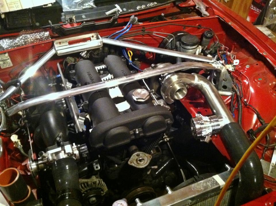
Top view. The part I'm proudest of - NO MAJOR CUTTING. The only modifications to the unibody was ending the edge on the radiator support to a 90 and trimming some of the lip on the frame rail to clear the radiator tabs (see above). You can see below there's plenty of clearance between the radiator and support while I still have a ton of room for aftermarket sways/fans and the hood has a good 3/8" - .5" of clearance. Once everything is finalized I'll create some ABS ducting.


I'm at a bit of a standstill in the engine bay until the Fed Ex man shows up with some parts so I started messing with the interior and installing/wiring my AEM gauges. I'm a wideband, boost, and water temp in center console. Surprisingly I didn't have to trim too much of the dash to fit the center gauge as they are pretty shallow. I plan on using the AC button on the HVAC panel to operate the hazards - more to come on that.

The Profec is going away since I'm using the MSPNP EBC (for sale, offers welcome - need to fund some DW injectors). I'm also working on the cluster which is missing in the pic. I gutted the stock coolant temp gauge and mounted an LED shift light behind the check engine/airbag, etc. window on the cluster which perfect in terms of visibility.

More pics as they come.
-Zach
I apologize for the pictures. I was working by candle light and with poor ISO on my camera and a lack of tripod there wasn't a lot I could do.
I've got the intercooler mounted and the cold side sorted out. The cold side was done with a 10" leg 90 degree elbow and a 30 degree 2.5" to 2.25" transition - vibrant coupler in between. I have enough clearence for a t-clamp, however, I ordered some gates 'heat shrink' clamps which I plan on using in an effort to save weight, look clean, and avoid potential chaffing. The IAT sensor is mounted on the coupler on the intercooler - maybe 18-22" upstream. As I said above, since the silicone is an insulator I'm not concerned with mounting the sensor upstream.
Top view. The part I'm proudest of - NO MAJOR CUTTING. The only modifications to the unibody was ending the edge on the radiator support to a 90 and trimming some of the lip on the frame rail to clear the radiator tabs (see above). You can see below there's plenty of clearance between the radiator and support while I still have a ton of room for aftermarket sways/fans and the hood has a good 3/8" - .5" of clearance. Once everything is finalized I'll create some ABS ducting.
I'm at a bit of a standstill in the engine bay until the Fed Ex man shows up with some parts so I started messing with the interior and installing/wiring my AEM gauges. I'm a wideband, boost, and water temp in center console. Surprisingly I didn't have to trim too much of the dash to fit the center gauge as they are pretty shallow. I plan on using the AC button on the HVAC panel to operate the hazards - more to come on that.
The Profec is going away since I'm using the MSPNP EBC (for sale, offers welcome
- need to fund some DW injectors). I'm also working on the cluster which is missing in the pic. I gutted the stock coolant temp gauge and mounted an LED shift light behind the check engine/airbag, etc. window on the cluster which perfect in terms of visibility.More pics as they come.
-Zach
Reply
0
0
06-11-2011, 03:24 PM
#14
Senior Member
Thread Starter
iTrader: (3)
Join Date: May 2005
Location: Mass.
Posts: 811
Total Cats: 43
Been a while since I've updated.
I haven't made much progress under the hood as of late as I'm waiting for a couple pieces of the puzzle to arrive. I've got the hot side of the intercooler piping to still fabricate and once that's done the motors coming out for some freshening an a happy meal.
In the mean time, I finally got around to mounting the fancy Magic Racing mirrors I picked up before exchange rate went into the *******.
I still need to counter sink the mounts some - I took a guess before I had the hardware. Try buying 4 pinned torx metric screws in the States. I ended paypal'ing a guy in Britain to mail me some.
IMO, it's like these mirrors were made for these cars. The 'softer' surfacing and proportions fits well the the car and the curvature of the lens provides ample viewing.
I apologize for the phone pics.


-Zach
I haven't made much progress under the hood as of late as I'm waiting for a couple pieces of the puzzle to arrive. I've got the hot side of the intercooler piping to still fabricate and once that's done the motors coming out for some freshening an a happy meal.
In the mean time, I finally got around to mounting the fancy Magic Racing mirrors I picked up before exchange rate went into the *******.
I still need to counter sink the mounts some - I took a guess before I had the hardware. Try buying 4 pinned torx metric screws in the States. I ended paypal'ing a guy in Britain to mail me some.
IMO, it's like these mirrors were made for these cars. The 'softer' surfacing and proportions fits well the the car and the curvature of the lens provides ample viewing.
I apologize for the phone pics.
-Zach
Reply
0
0
04-13-2012, 08:53 AM
#15
Senior Member
Thread Starter
iTrader: (3)
Join Date: May 2005
Location: Mass.
Posts: 811
Total Cats: 43
One baby step closer to the finish line - finished the hot side.
Time to pull the motor and get this engine bay done with.
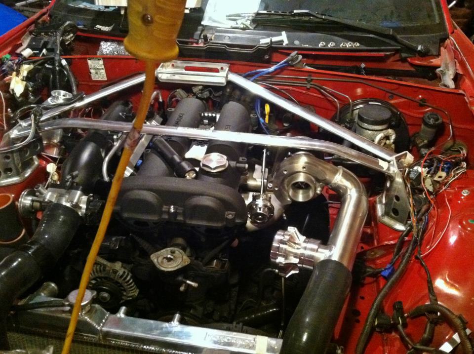
Over compensation - my BOV is a big as my turbo
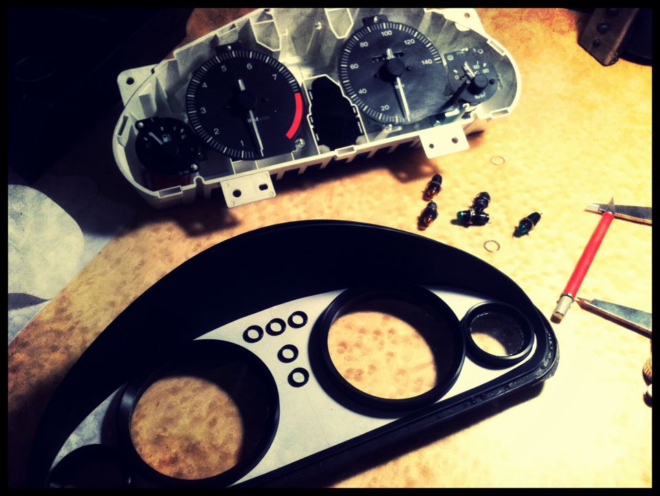
Also getting work done on the gauge cluster. The nickle is a placeholder for the LED shift light and the black rings will be LED dome lights for blinker/high beam and oil press/temp warning lights.

Hope to have this crap heap on the road by end of August at this point.
-Zach
Time to pull the motor and get this engine bay done with.
Over compensation - my BOV is a big as my turbo
Also getting work done on the gauge cluster. The nickle is a placeholder for the LED shift light and the black rings will be LED dome lights for blinker/high beam and oil press/temp warning lights.
Hope to have this crap heap on the road by end of August at this point.
-Zach
Reply
0
0
04-16-2012, 04:22 PM
#16
Senior Member
Thread Starter
iTrader: (3)
Join Date: May 2005
Location: Mass.
Posts: 811
Total Cats: 43
Stupid question:
If you have a variable TPS sensor, will unmodified MSpnp translate the sensor outputs as though it's a non-variable TPS or will it just tell you to f*ck off?
Even though it's a simple mod to the MS, I don't want to crack it open until I'm able to confirm it is fully operational from the vendor.
-Zach
Reply
0
0
04-23-2012, 12:00 PM
#17
Senior Member
Thread Starter
iTrader: (3)
Join Date: May 2005
Location: Mass.
Posts: 811
Total Cats: 43
No response? wha wha...
No pics but my CC took it's last big hit courtesy of FM and Trackspeed (can't wait to pay it off this month )
)
FM
-misc. seals and tools to install said seals
-FM happy meal, 10 pound flywheel w/ level 2 clutch (went overkill)
-exhaust brace
-8mm inconel studs for DP
-clutch line
Trackspeed
-10mm inconel stud kit
With the new hardware, my only failure point should be my ---- manifold cracking especially since I expect to be very slow around the track if and when that day comes
Another question for the 1.6 folk: anyone know the threading of for the coolant feed on the side of the 1.6/GTX block? (the one above the oil feed greddy/FM uses).
-Zach
No pics but my CC took it's last big hit courtesy of FM and Trackspeed (can't wait to pay it off this month
)FM
-misc. seals and tools to install said seals
-FM happy meal, 10 pound flywheel w/ level 2 clutch (went overkill)
-exhaust brace
-8mm inconel studs for DP
-clutch line
Trackspeed
-10mm inconel stud kit
With the new hardware, my only failure point should be my ---- manifold cracking especially since I expect to be very slow around the track if and when that day comes
Another question for the 1.6 folk: anyone know the threading of for the coolant feed on the side of the 1.6/GTX block? (the one above the oil feed greddy/FM uses).
-Zach
Reply
0
0
04-23-2012, 10:42 PM
#18
Senior Member
Thread Starter
iTrader: (3)
Join Date: May 2005
Location: Mass.
Posts: 811
Total Cats: 43
Until I find my Pana Lumix battery charger ... the ---- cell phone pics will continue (and yes, I'm hosting w/ Facebook )
Since the car is garaged an hour away, I gotta make progress where and why I can. Tonight's project was to replace my deteriorated coolant tank. While the Moroso replacement is nice, I needed to stop the bleeding and I already had a universal Moroso tank on hand.
Turns out it fits perfectly onto the OEM fuse box bracket:
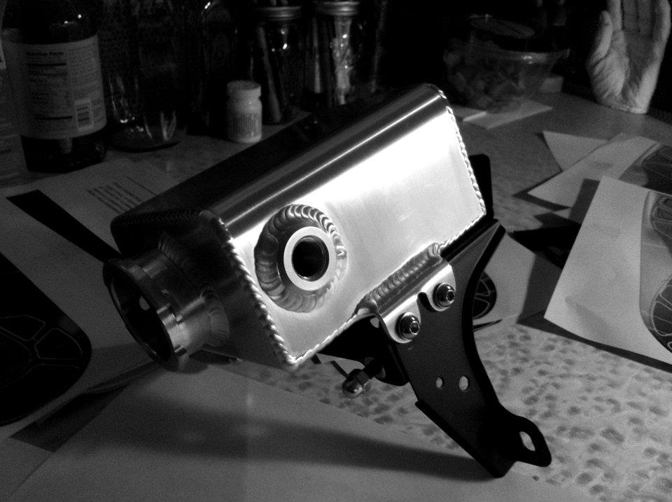

Yes, the mounting looks like crack-city but the weight is primarily supported by 3m VHB ... the hardware is just along for the ride.
I realize I'm losing some fluid capacity but hopefully that won't be an issue with the added capacity of the radiator along with some competent ducting TBD.
Motor to come out this weekend and preparation for a 'bay respray, seals refresh, FM 'happy meal', and misc. sh_t.
-Zach
)Since the car is garaged an hour away, I gotta make progress where and why I can. Tonight's project was to replace my deteriorated coolant tank. While the Moroso replacement is nice, I needed to stop the bleeding and I already had a universal Moroso tank on hand.
Turns out it fits perfectly onto the OEM fuse box bracket:
Yes, the mounting looks like crack-city but the weight is primarily supported by 3m VHB ... the hardware is just along for the ride.
I realize I'm losing some fluid capacity but hopefully that won't be an issue with the added capacity of the radiator along with some competent ducting TBD.
Motor to come out this weekend and preparation for a 'bay respray, seals refresh, FM 'happy meal', and misc. sh_t.
-Zach
Reply
0
0
05-02-2012, 09:06 PM
#19
Senior Member
Thread Starter
iTrader: (3)
Join Date: May 2005
Location: Mass.
Posts: 811
Total Cats: 43
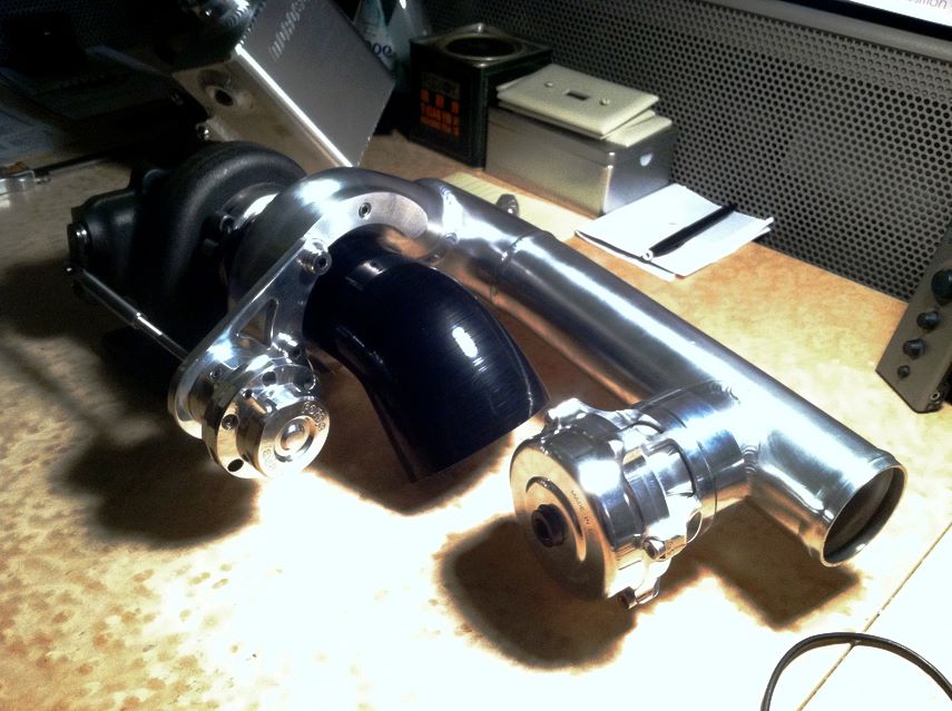
Finally got around to making the wastegate bracket.
I always hated the shitty canister which comes on the Greddy turbo. So when I saw a vendor off loading Forge wastegates for the MS Protege for <$70 ... I hit buy hoping I could make it work.
Turns out it fits perfect. I used .25" 6061 aluminum in an effort to limit bracket flex.
Now that everything is fitted, I can send the hot parts off to the ceramic coater.

-Zach
I always hated the shitty canister which comes on the Greddy turbo. So when I saw a vendor off loading Forge wastegates for the MS Protege for <$70 ... I hit buy hoping I could make it work.
Turns out it fits perfect. I used .25" 6061 aluminum in an effort to limit bracket flex.
Now that everything is fitted, I can send the hot parts off to the ceramic coater.
-Zach
Reply
0
0
05-02-2012, 09:10 PM
#20
Cpt. Slow
iTrader: (25)
Join Date: Oct 2005
Location: Oregon City, OR
Posts: 14,360
Total Cats: 1,184
Nice bracket! A lot of people get hung up on wastegate brackets, OEM brackets are stamped steel, hard to duplicate, and people get hung up on where to go from there. Flat sheet steel just bends.
Reply
0
0


