When you click on links to various merchants on this site and make a purchase, this can result in this site earning a commission. Affiliate programs and affiliations include, but are not limited to, the eBay Partner Network.
Contact Energy Suspension directly. Tell them you bought it from us "recently". Tell them what part of the BOM is wrong and what you need. They'll ship one out.
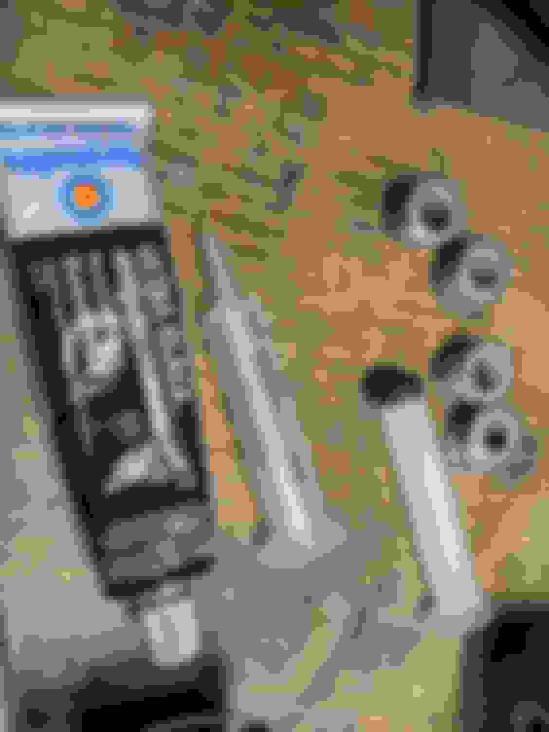
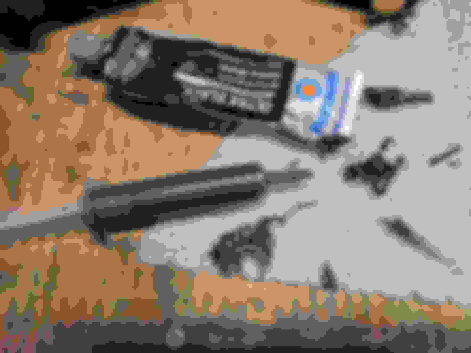
bout 5 years ago, we began hand counting each kit because 15 years later, ES is still incapable of packing one right. About an hour ago, Sonny was packing a kit that had too many bushings, a few of which weren't even Miata parts.
Contact Energy Suspension directly. Tell them you bought it from us "recently". Tell them what part of the BOM is wrong and what you need. They'll ship one out.
bout 5 years ago, we began hand counting each kit because 15 years later, ES is still incapable of packing one right. About an hour ago, Sonny was packing a kit that had too many bushings, a few of which weren't even Miata parts.
Sounds like someone was cleaning off their workstation at the end of a shift or something, lol.
Contact Energy Suspension directly. Tell them you bought it from us "recently". Tell them what part of the BOM is wrong and what you need. They'll ship one out.
bout 5 years ago, we began hand counting each kit because 15 years later, ES is still incapable of packing one right. About an hour ago, Sonny was packing a kit that had too many bushings, a few of which weren't even Miata parts.
Hi @emilio700 ! Not sure why you have any interested in my pile of garbage but thanks for stopping by!
I'll shoot Energy customer service an email this afternoon, thanks very much for the advice! As a point of reference, its order from 9/26/2012
Originally Posted by boileralum
Sounds like someone was cleaning off their workstation at the end of a shift or something, lol.
I've seen much, much worse. Back when I was playing with 1st generation Mustangs a supplier would straight ship the wrong part and then tell the vendor and the customer that it was "production variance" or "someone change the parts in the last 40 years" which would lead to chaos and the destruction nigh irreplaceable 40 year old factory parts. I'm sure Energy will make it right, but not before the end of the weekend.
Originally Posted by dleavitt
Sounds like I should spend a few minutes checking my bushing kit before I get too excited.
I've been doing this for enough years that I *SHOULD* check things like this, but in practice I never get around to it. LEARN FROM MY MISTAKES!
Originally Posted by dleavitt
Did you bother with RTVing the grooves in the ES bushings?
I haven't done it yet, but I'll do it right before final lube, assembly and install. There is an absolute shitload of hydraulic pressure in an industrial grease gun so I don't know how much difference it'll make, but the grease will absolutely flow in the direction of least resistance. Doing nothing is definitely the path of least resistance so I'm going to want something in there. I'll probably cut down the tip on a plastic medical irrigator syringe and fill it with UltraBlack, fire some in there and hope for the best. Gotta wait for the load spreading washers to get here.
Originally Posted by codrus
So this is moot, but I was going to say that if I wanted to cut down a poly bushing I'd probably use a razor blade instead of a lathe.
And while I agree with you on principal, I feel like I'd have more control with the frozen bushing and a razor sharp cutter on the lathe rather than free-handing on the bench with a razor blade. Although I'd be lying if I said I hadn't spent about 20 minutes drinking beer and trying to figure out how to mount a razor blade in the lathe, which is quite the scary proposition
One of the worst things I've ever had to work with in a lathe was 1" diameter Teflon bar stock for a production run of bushings. The jaw force in the hydraulic collet chuck was critical, to tight and it would compress the teflon to the point where it would expand after you made the cut and throw the part out dimensionally. Not tight enough and the tool would just push the bar back into the chuck during the drilling operation. It also wouldn't break a chip to safe its life so you were fighting a huge rats nest of chips, and the parts were small enough and light enough that they wouldn't make it on the part-off tray so you'd have to fish them out of the bottom of the lathe. All 1500 of the damn things. I hate Teflon. And polycarbonate. Titanium was easier to work with than Teflon. Hell, so was Inconel, and that stuff work hardens like nothing I've ever seen. Ungh.
usps came through to save the day? I dont believe you.
Truth be told I'm struggling to believe it myself!
This was a truly miserable task.
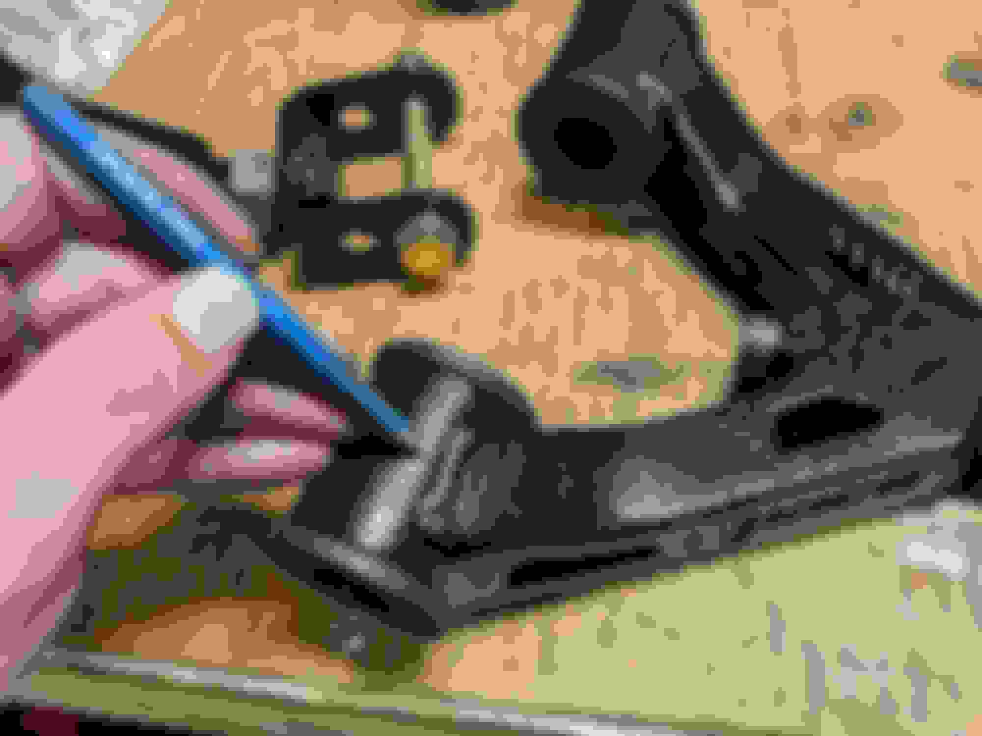
Tube of RTV was blocked up so I gave up and snipped off the corner.
These are about the only pictures I took, because this **** got EVERYWHERE and I preferred not to have it all over my phone. The syringe thing actually worked out pretty well, though I did end up pushing additional RTV into the grooves with my thumb, then cleaning the crush sleeves as best I could.
Fancy stainless washers went in without issue, and then the arms went back in the car. Suspension is fully reassembled, minus shocks and springs, and of course minus the driver's side FLCA that's missing a bushing. Turns out I'm mildly 'tarded and most of the locations I picked for the grease zerks are pretty bad, and I can't get to at least 1/3 of them without disassembling something else. Definitely going to see if I can find a 90� adapter head for my grease gun. Barf. I'll take some pics later so you guys can learn from my copious mistakes :P
Looks like we're scheduled for rain every day for the next full week, outside of tomorrow, so I best get to steppin' if I'm going to get the rest of this thing back together. 😬
I neglected to mention previously that I picked up a set of Paco Motorsports Adjustable Rear Upper Control Arms. They had the parts on sale and I can't resist touching things I have no business touching, and I feel like having "field adjustable" rear camber might be a welcome addition.
They are very nice parts, almost too nice for this car. Energy Suspension poly bushings fit just fine, as do the SADFab sleeves.
Of course the big question was where to put the grease zerks? The SADFab instructions warn us that the location is critical due to the "strap" at the bottom edge of the opening between the two eyes where the RUCA-I mounts to the subframe, it'll shear off the zerk at full droop if its mounted in the wrong spot. As that seemed like a bad time, I decided to mount them on the top. I thought there was enough clearance...
I just love drilling holes in brand new parts, lol
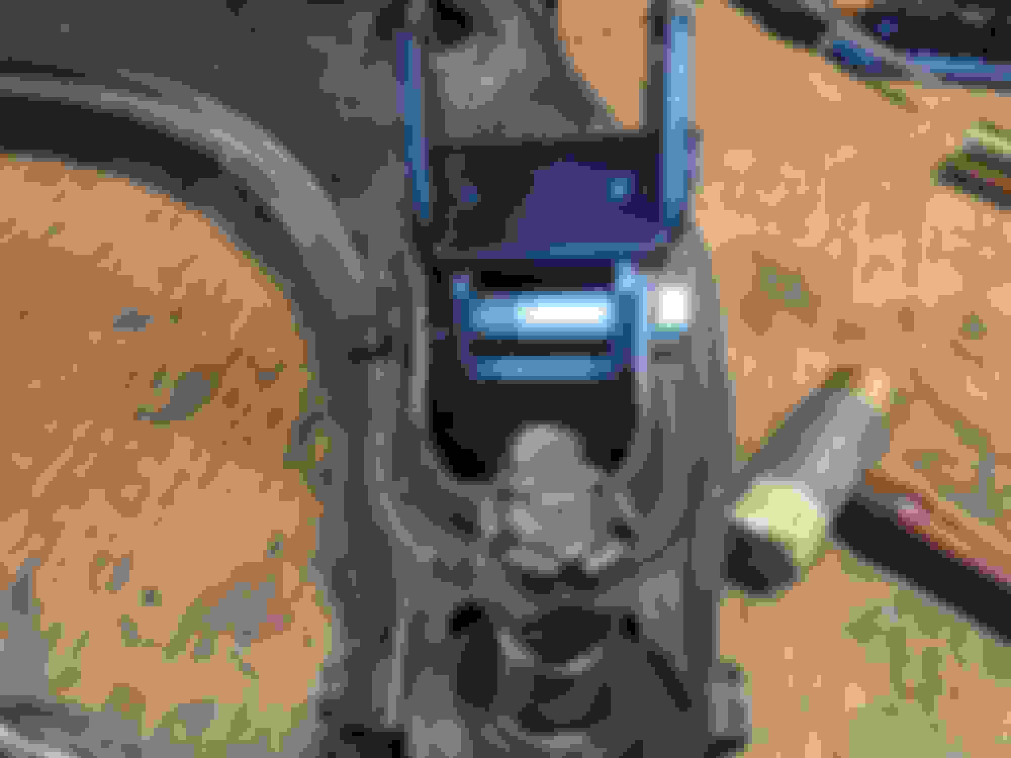
And there we go! You can swing the arm up until it hits the tub and the zerks don't touch the subframe. Unfortunately I juuuuust can't quite get my grease gun nozzle in there due to the lip on the subframe.
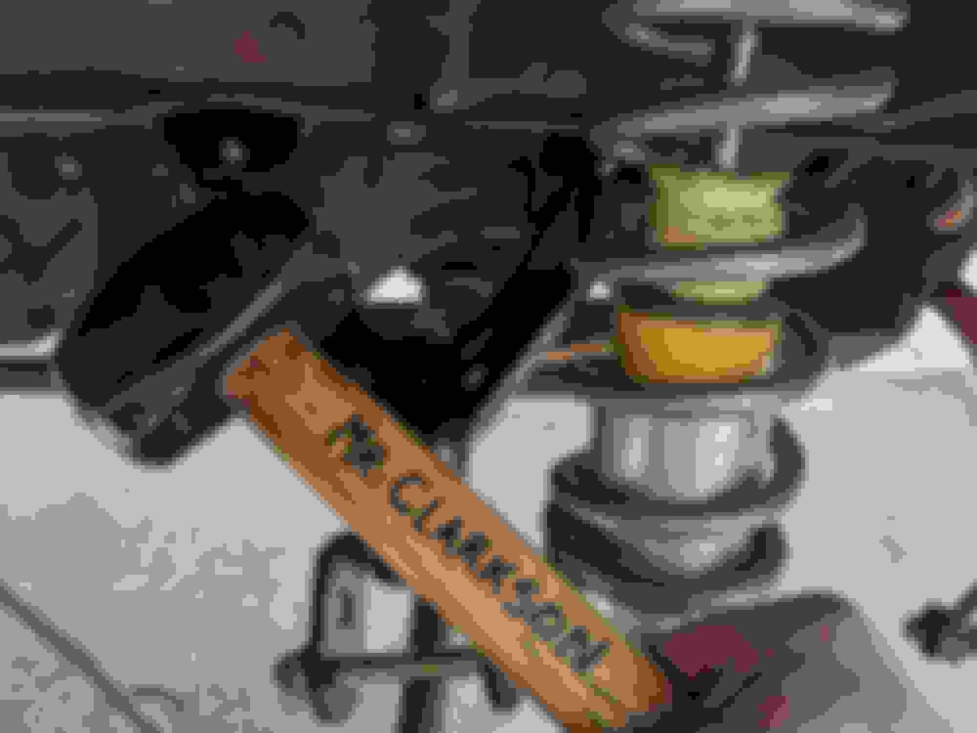
I pulled "Mr. Clarkson" out of the tool box and let him have a go at it (with the arm removed, as one does)
And now I can get my grease gun in there! Kinda! The angle sucks and I can't get a good seal on the nipple so its not a great solution. For now I'll get a 90� attachment for my grease gun, but at some point in the future I'll probably drop the subframe and grind a clearance notch in that lip.
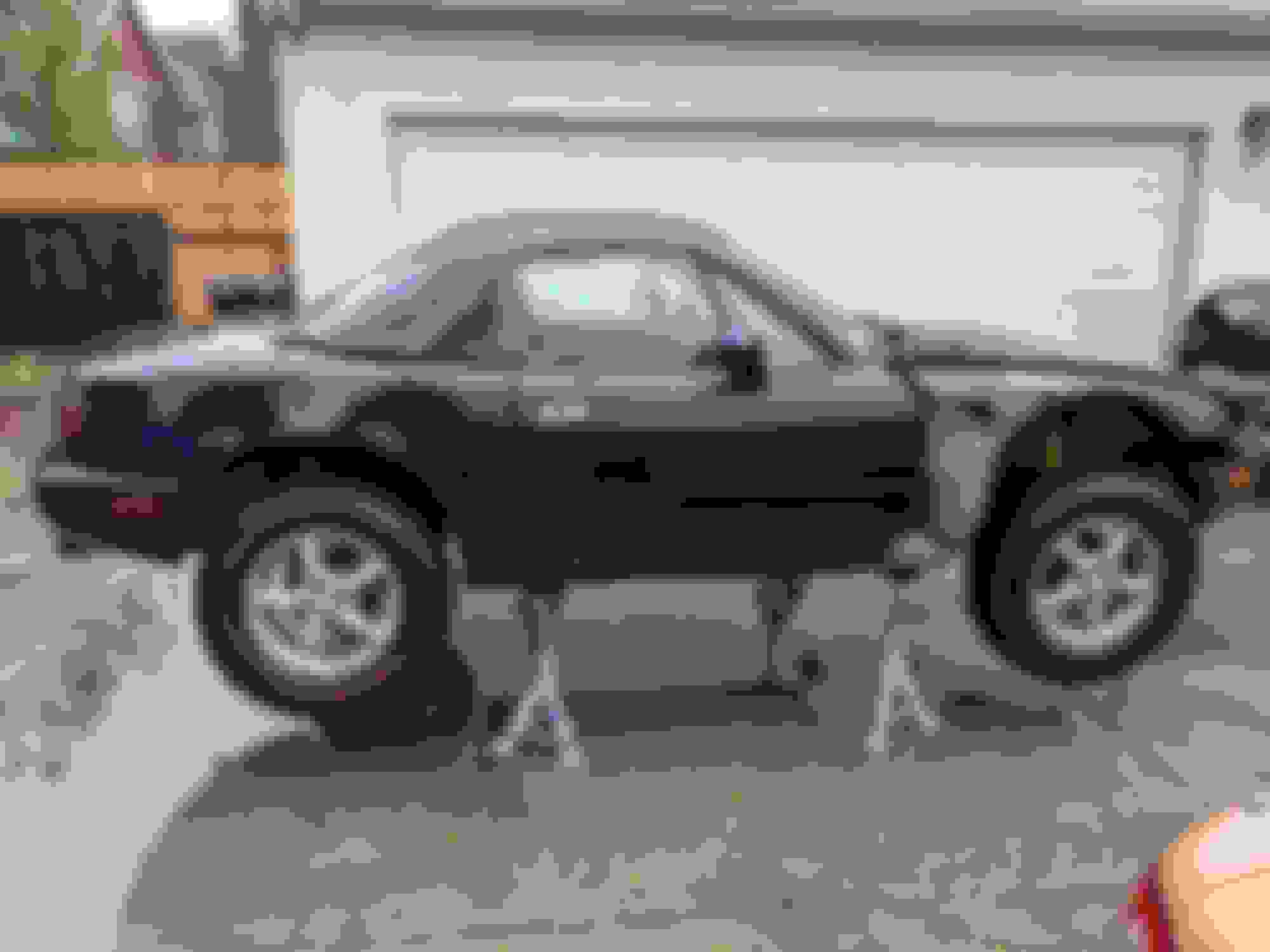
In keeping with the "stupidest sequence of worst decisions" mantra, I got the Paco lift on the car this last week
Well, mostly installed. The rear is "done" and front is still waiting for the replacement bushing from Energy so I can reinstall the FLCA.
The grand idea here is something that I can use for both the Lemons Rally, the private "Gambler 500" style event that I've done annually for the last few years, and if it all works well, maybe, just maybe, something like the Baja XL Rally in 2022, but that's getting WAY ahead of myself in this project.
This decision actually goes waaaay back to when I initially acquired the car, I've been sitting on the lift kit parts for months and a lot of the bits and pieces I've already shared are in support of the lift. I'll dig into the gruesome details here shortly, but I wanted to get some things out of the way first.
First things first, nobody actually needs a lifted Miata, and I would not recommend building one. In fact, I was actually a bit on the fence about sharing this project because I didn't want to encourage other people to cut up perfectly good chassis for gross stupidity. This of course begs the question, then why am I building one? Well, if you've been following this thread at all, you'll see this chassis is roached. What I'm doing to this car borderlines on the retardation we get from the drift kids, and driving cars into walls is not something I'm willing to encourage either. One of the reasons I jumped on this particular project for this particular chassis is the direct previous owner actually said they were going to strip and crush it, so it seemed like a solid candidate for gross stupidity.
I want to give a shout-out @Scaxx for his very fine Brad gets beatbuild thread, and for suffering through the eleventy billion chat messages we've shot back and fourth at each other over the last 4 months. I'm sure I've greatly impacted his work productivity but I appriciate his efforts none the less. If you want a solid technical discussion of Paco things with maths, I'd wholeheartedly recommend his thread. I'm not going to go into that kind of detail, I'm just here for brute force and ignorance.
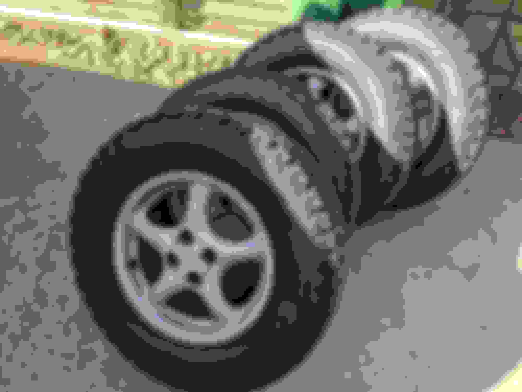
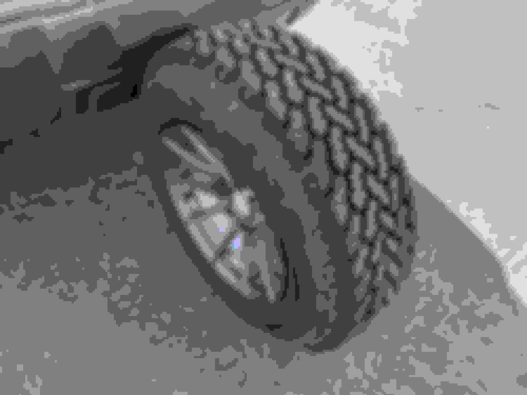
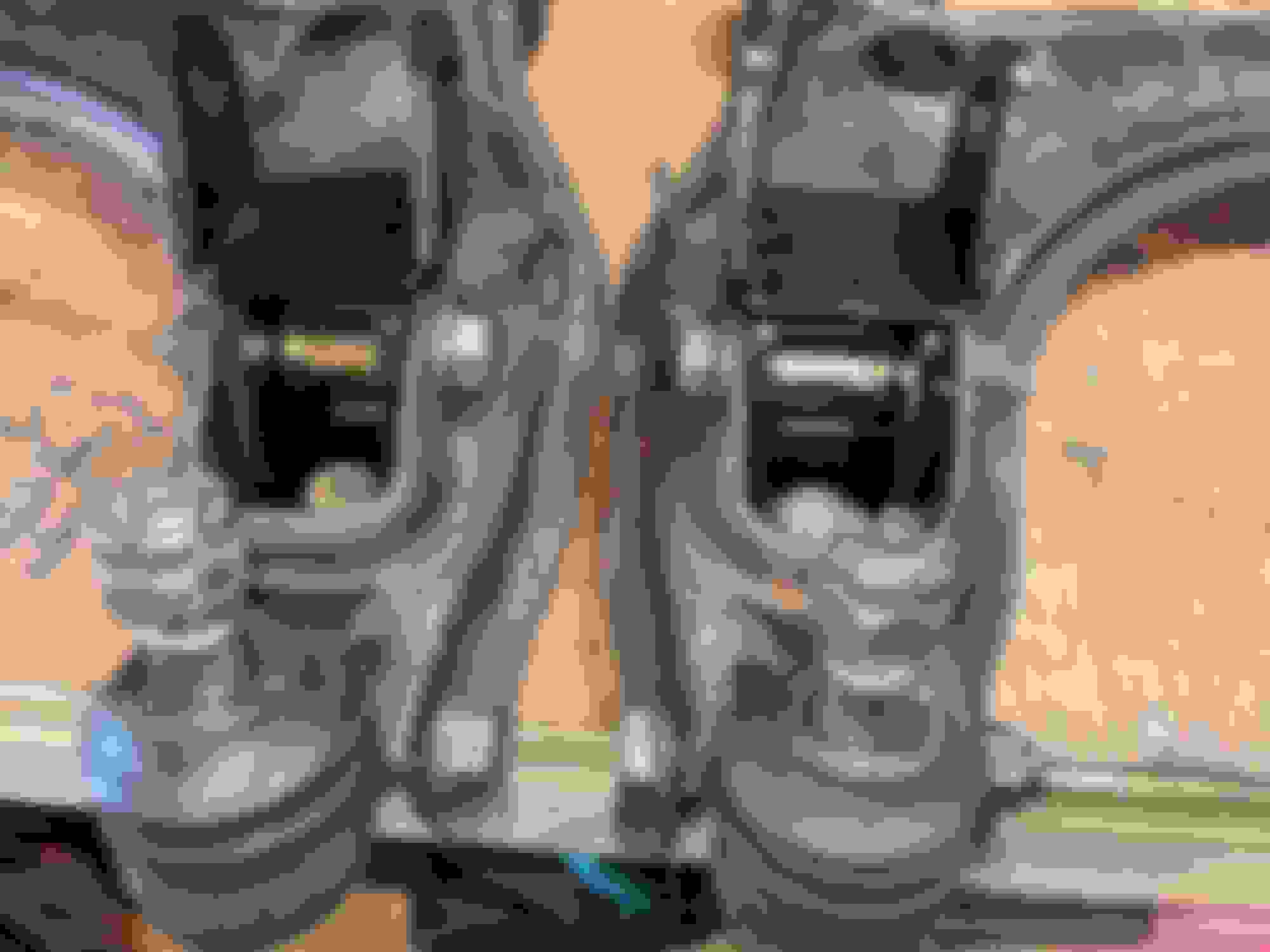
The tires I've selected are General Grabber AT2s in 215/75 R15. I bought these MANY months ago, and it looks as though General *may* have discontinued this size. Which is awesome. I'm glad I bought 5, and I may buy a 6th as a "cold" spare.
You know, how ******* hard is it to remember "white letters out" when you deal with the tire guys.
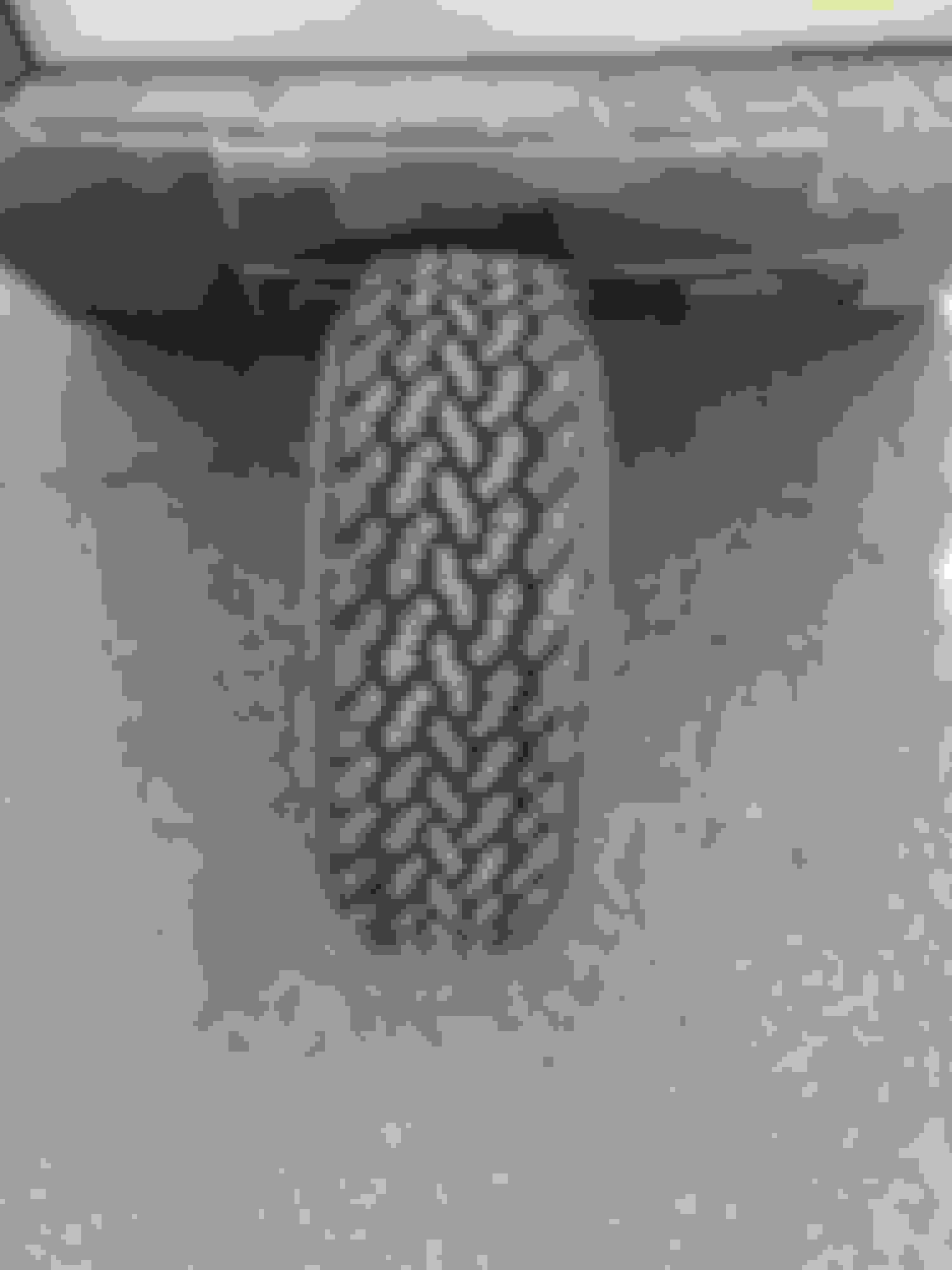
Everyone loves a tire size comparison money shot:
**** that is ignorant
And of course you can't put General Grabbers on *ANYTHING* without some flat billed sleeve tattood meathead saying "Bro, why didn't you buy red letter Grabbers, bro?"
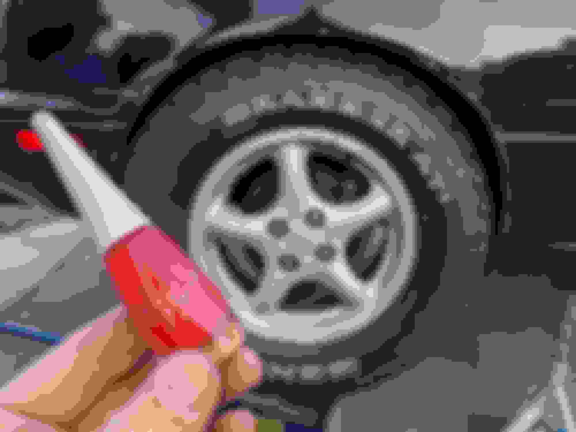
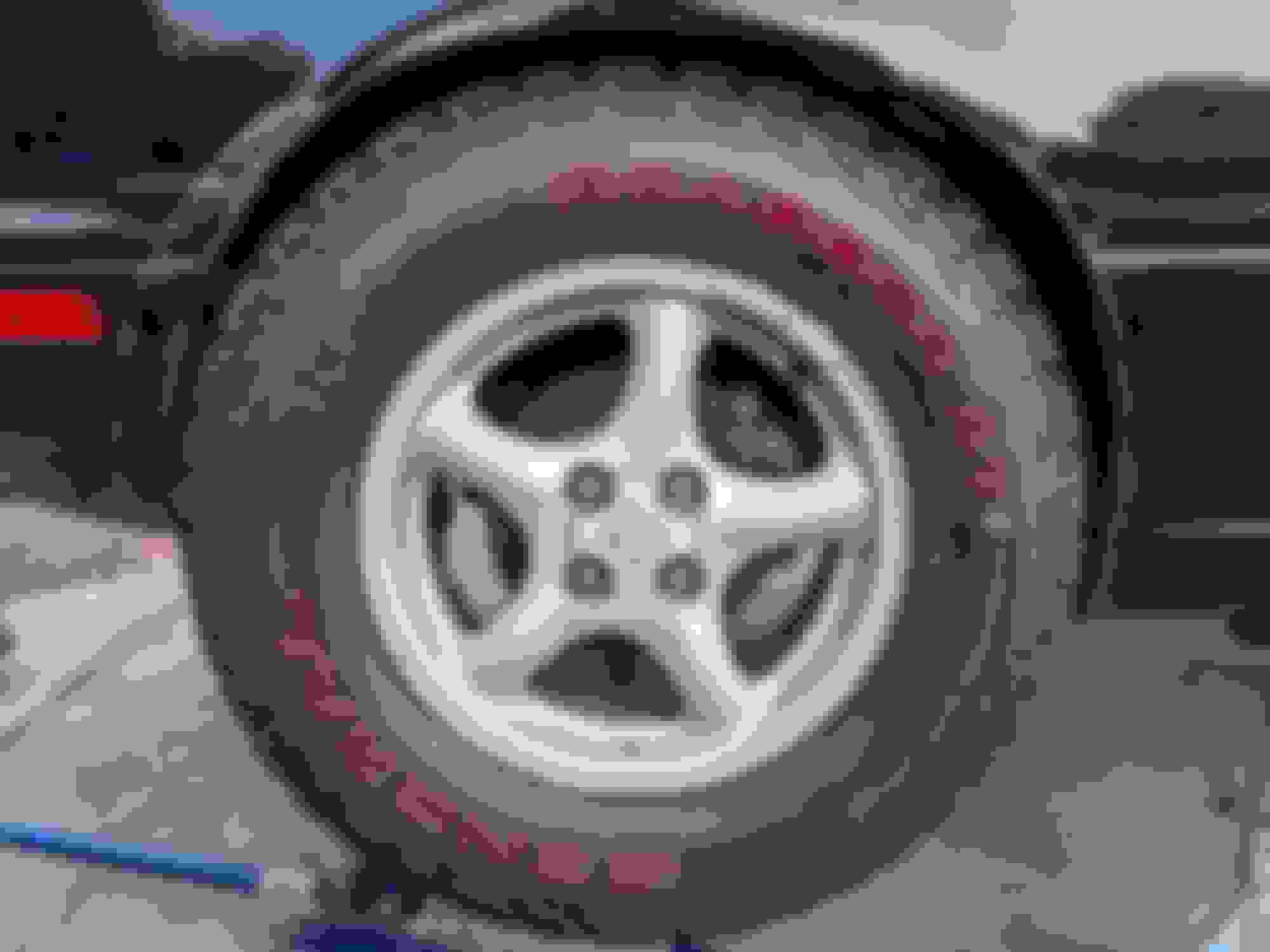
So you know what? I made some.
For those wondering, the color is Mary Kay Signature Series "Red Hot"
Bam! Red Letter Grabbers on a Miata! You saw it here first! the Cars and Coffee guys are going to love this.
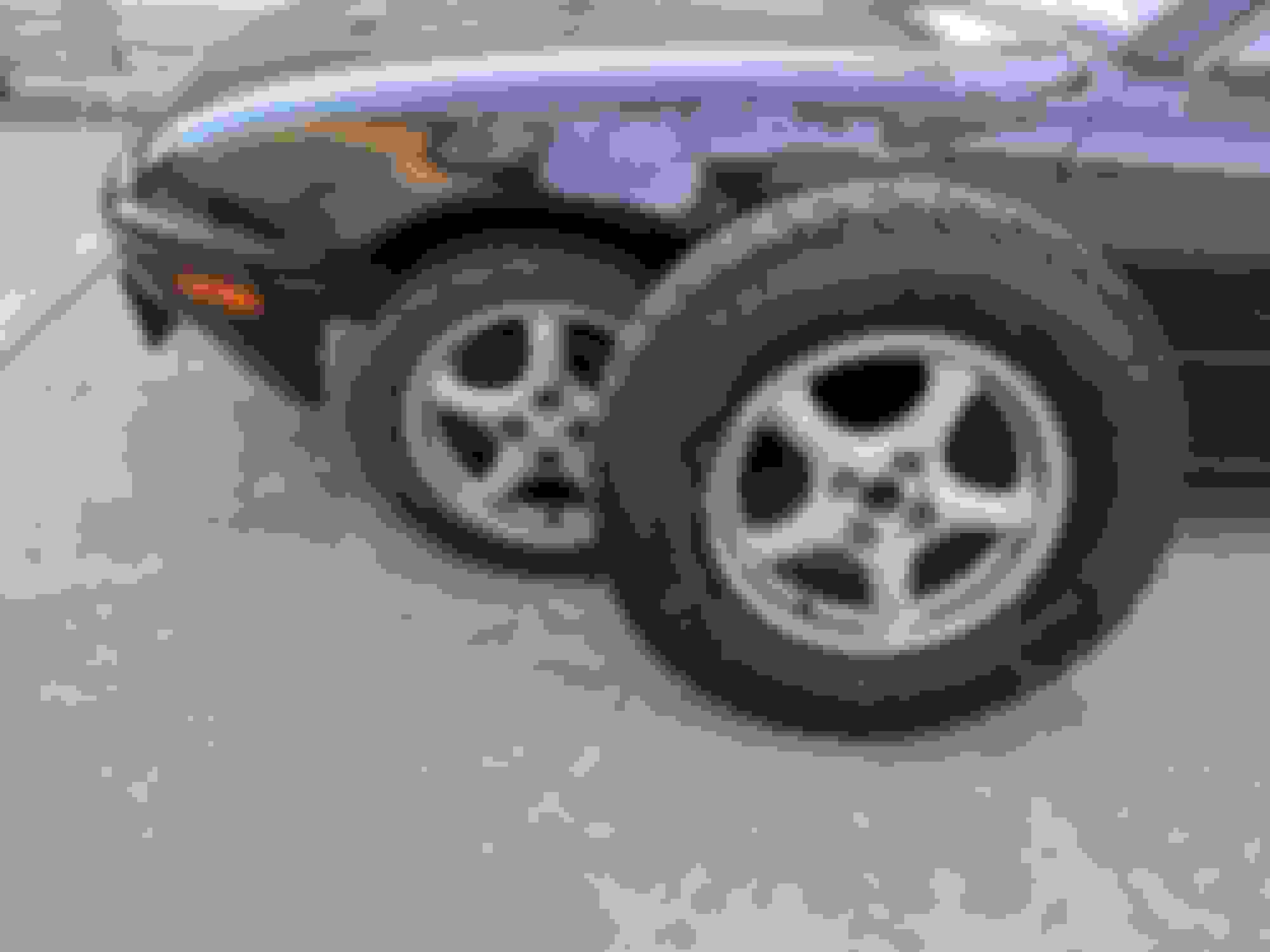
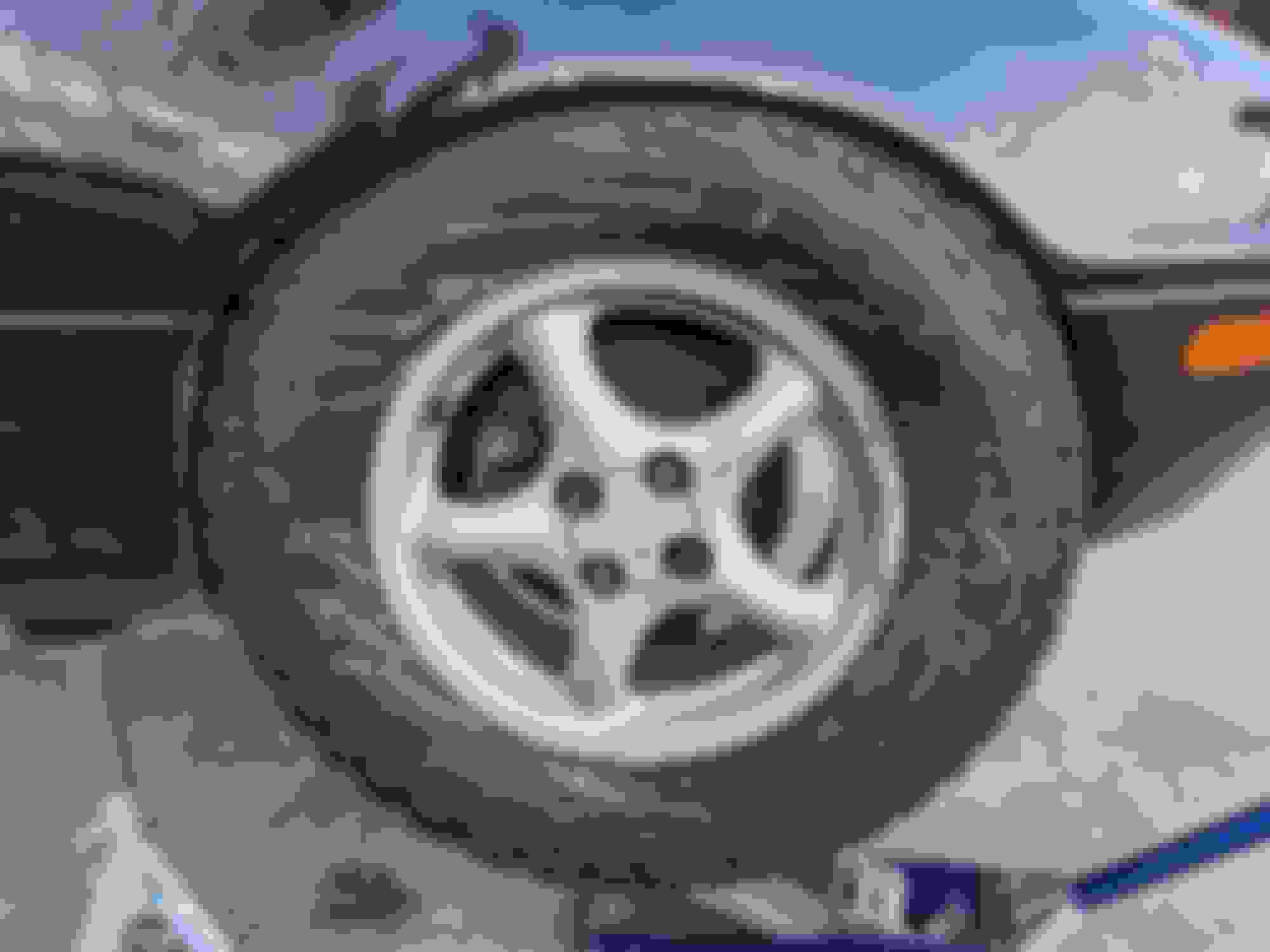
The rims are of course stock NB 15x6, and I'm running them with a H&R DRS TRAK+ 30245410 spacer to try to push the wheel out slightly. These are 15mm thick spacers with correct Miata specific 54.1mm hub centric lip on both the inside AND outside to correctly locate the rim on the hub. Generic flat spacers in this application freak me out so I was glad to see the H&R ones are properly designed. I'm sure ARP studs are "fine" but I figured Mazda put the lip in there "in shear" for a reason, so I wanted to maintain that feature, especially since I' pushing out a bit past what Mazda intended. With the ARP extended studs and stock style steel lug nuts (chrome, of course) I still have full engagement with the stud threads.
Initial test fit with the spacers in the rear looks good. I'll cover fender clearance things later.
Excellent fit
And full thread engagement with an open top steel lug nut.
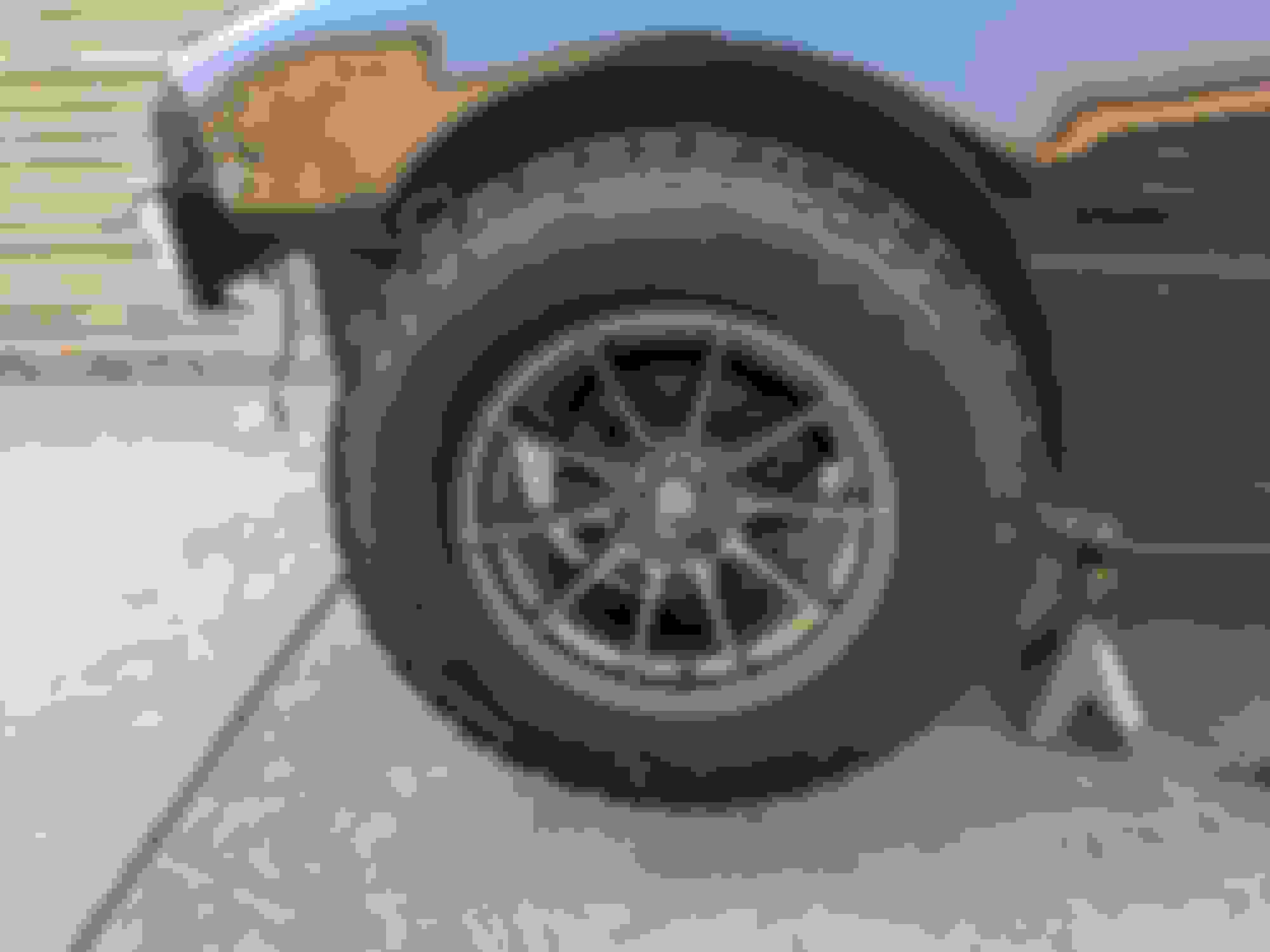
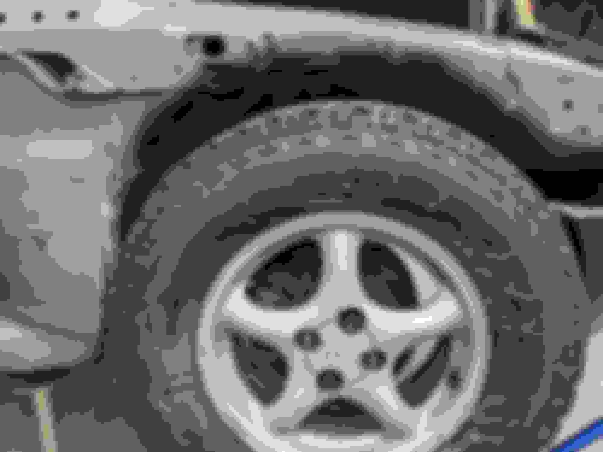
I initially tried to use the 15x8 Storm S1s that came on the car, but that fitment was problematic.
AT tires don't exactly follow the same fitment rules as street car tires and that much sidewall bulge is going to be a liability when playing in the dirt. I still think it would have looked cool as **** though. I managed to find a pair of stock 15x6s semi locally, so at least now I have a couple spare rims.
The young guy I bought these from was "getting out of Miatas" because they are "getting too expensive" and you "can't get them cheap enough anymore." I felt bad for the d0r1ft0 spec CTS in his driveway.
I will admit my choice of tire size could have been better. Not that I'm trying to "one up" Scaxx on tire size, buuut...
The tires Scaxx picked out are 26.3" OD and are a much more "appropriate" fitment for the car, where as my 27.7" tires are going to be ... challenging. That extra inch and a bit takes you from "almost direct fit" to "GRINDER GO BURRRRRR!!!" If you want to see crazy fitment with dirty offset, check out @hedtrip and his The lifted Mazdaspeed thread. I believe he's running 235/75 R15s on Bassett circle track steelies. His fitments are a bit different because its an NB, but its a solid reference.
The 4.77 gears I bought a while back are a direct result of selecting this tire size and the gearing on this thing is gonna be fuuuuucked with a 4.1. Here is the FM Gearing Calculator with a "reasonable" Miata tire size, 4.1 diff and 5 speed:
And here are those same calculations for my 27.7" tires, 4.77 diff and 5 speed:
You have to admit, that's pretty damn close. I've never found a Miata 5 speed with 4.1 diff to be "lacking" so this plus whatever extra grunt is provided by the M45 should be "good enough." There was initially some drive to get me to buy 5.38:1 gears, but those ******* are like $450. My Kia 4.77s were under $300 to my door, including insane overseas shipping rates. I call that a win. I may end up driving this car for thousands of miles, both on and off road, so I'd like it to at least be able to get out of its own way.
I'll gather some more pics and make a couple more posts this afternoon about the lift itself, clearances, and body mods. I've been excited to let this one out of the bag
for the absolute wonderful stupidity that is this car and build thread. My tires might fit better, but damn those looks awesome. I can't wait to see the finished product!
The lift itself came from Paco Motorsports, I picked it up some months ago while it was on sale, plus free shipping, plus yadda yadda. You can also buy this from FM for more money but "free shipping." I would NOT recommend you buy this from FM, I'll touch on this a bit at the end of the post. The lift includes 4 brackets which relocate the lower mount point for the shocks down approximately 3" which in turn gives you approximately 3" of lift. They are literally just spacers, they do NOT add travel to the system.
The short, curly and stinky of it is that while this kit is functional, I'm a little disappointed in some of the details. I'll cover these as they come up.
One of the biggest things that irks me is the instructions. Paco didn't write their own and instead they send you to the FM instructions, which in a word, are godawful. I don't know who writes the instructions at FM but whomever it is has been doing it for years, and I've always disliked them. They are probably functional, but the "on car" photos are miserable busy and the arrows all over the place don't help. Both the images and arrows use the same numbering scheme so they'll say something like "Refer to #6" and you don't know if you are supposed to be looking at Image #6 or Arrow #6 while you are trying to read through an impenetrable wall of text. Miserable. Maybe its just me but I can't handle them, and I've been buying FM junk for years.
Another thing that bugs me quite a bit about the kit is that, without a doubt, its going to be a massive bastard to get the kit installed with the stock suspension and stock rubber bushings. The Energy Suspension poly bushings and SADFab sleeve retrofit went in specifically to deal with the bushing issue. @Scaxx has some pretty terrible anecdotes about 6' cheater bars trying to compress and move things far enough to get parts installed. F that noise, I'm all about dat sweet sweet articulation here. Gotta get my squeak on with these bushings.
Anyway, we'll start with the front end.
Install is fairly simple install as I'm sure you can imagine.
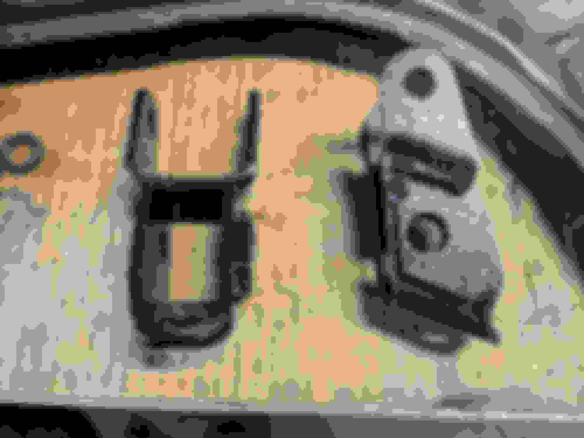
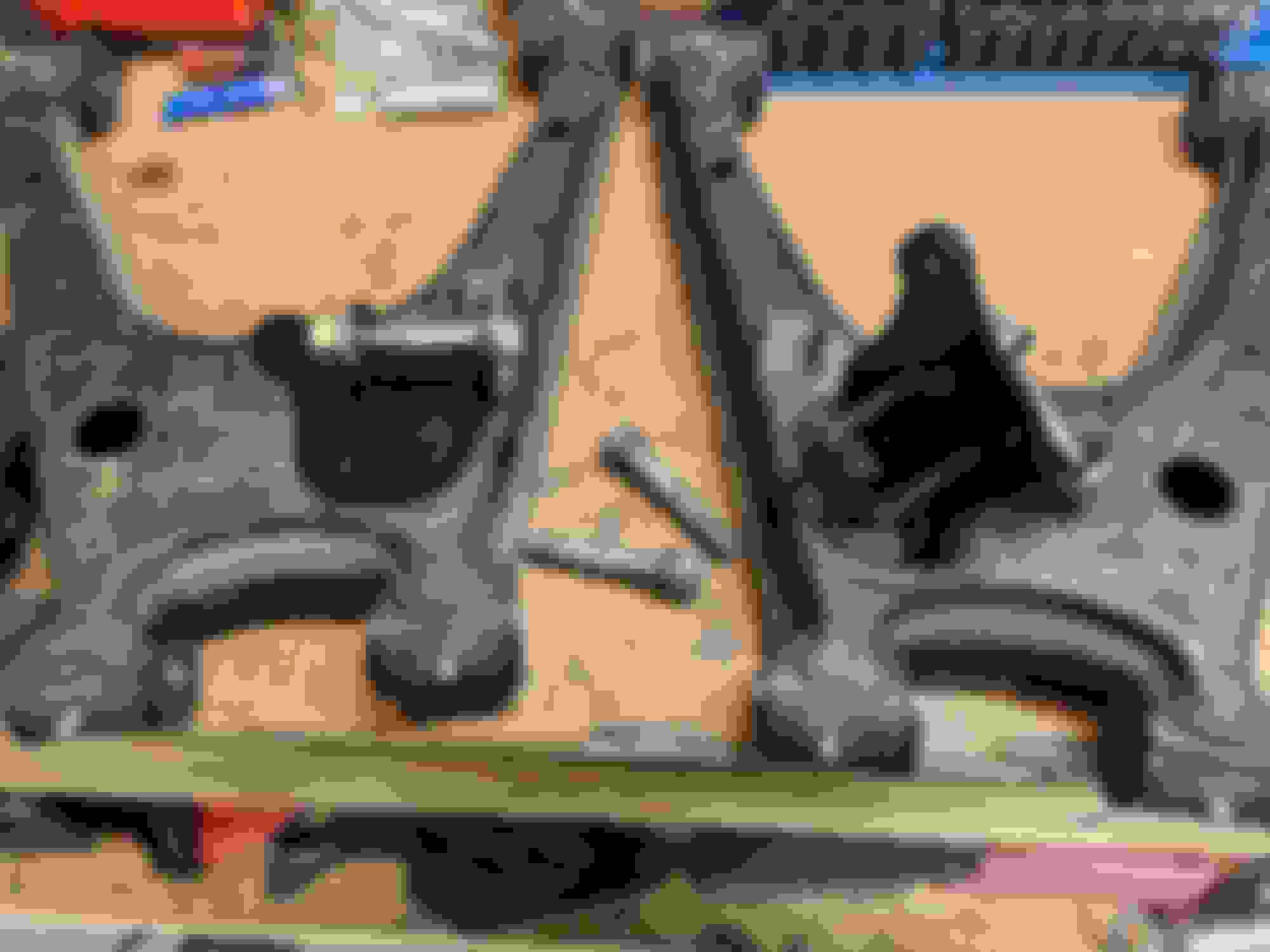
Here's the brackets
Heres another shot of the brackets. The thicker parts go... somewhere. Check the instructions for the orientation.
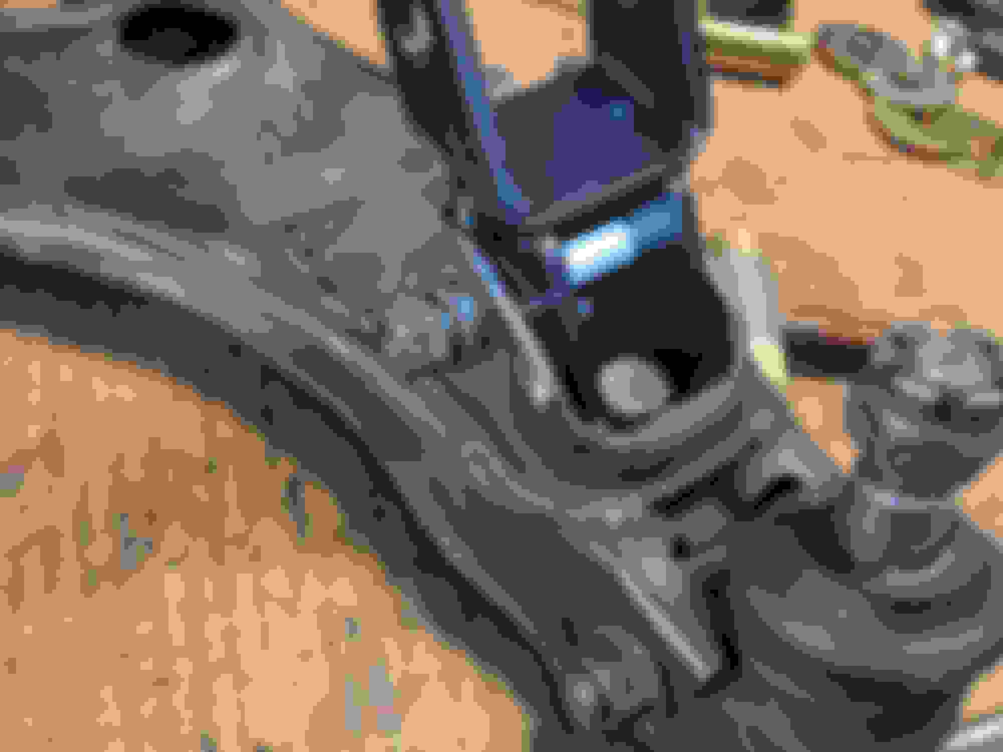
You don't have to remove the arms, but I already had them off to install bushings so it seemed like a good time to install.
It attaches with one of the LBJ bolts and the stock shock crossbolt.
Smack with hammer to seat it, good to go.
Now time to torque it down. The LBJ bolt is simply torqued to spec which I believe is 54-68 ft/lbs. Which is easy-peasy. The crossbolt for the shock is also torqued to spec, which is also 54-68 ft/lbs. Which is... going to ruin the ******* shock mount in the FLCA.
This is where some of my vitriol about FM comes into play. When I initially read the the instructions before buying the product from Paco, I also read the reviews on FMs website. I think there was around 10-12 reviews, some of them are not so great, but as FM indicates, we are kinda pushing the limits here so fitment issues may become apparent. Ok, I get that. Everyone has different tolerance for fuckery. Several months later after I ordered the kit from Paco and went to actually download the FM instructions, FM had removed the critical product reviews for the lift kit! The reason I noticed was there were several reviews that talked about the shock mounting and crushing the mounts, which I wanted to read again, but they were gone. In my book that's incredibly deceptive and it really pissed me off. </rant>
I went back and checked again today and the critical reviews are back. I'm sure this was a "website database error" or something equally "innocent" but it still pisses me off.
Anyway, there is no way in hell that piddly steel box is going to support anything near 54-68 ft/lbs of clamping pressure without deforming to ****, and a couple of the reviews on FMs site call them out on this issue. The stock shock assembly has a big thick steel crush sleeve inside the bushing, where as this has nothing. DANGER TO THE MANIFOLD! So what we need is some support in that locations that emulates the stock steel crush sleeve in the bushing.
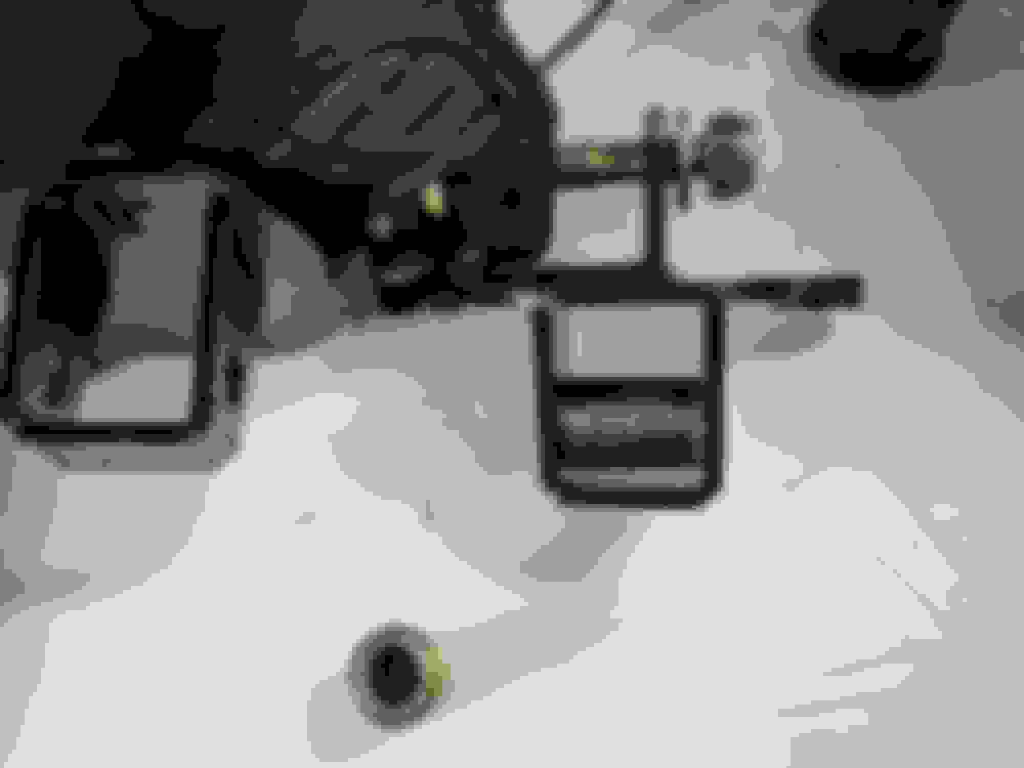
Take measurements
Then ignore the measurements. The fancy wrinkle powder coat over MIG welding slag spatter surface finish is not "precision friendly"
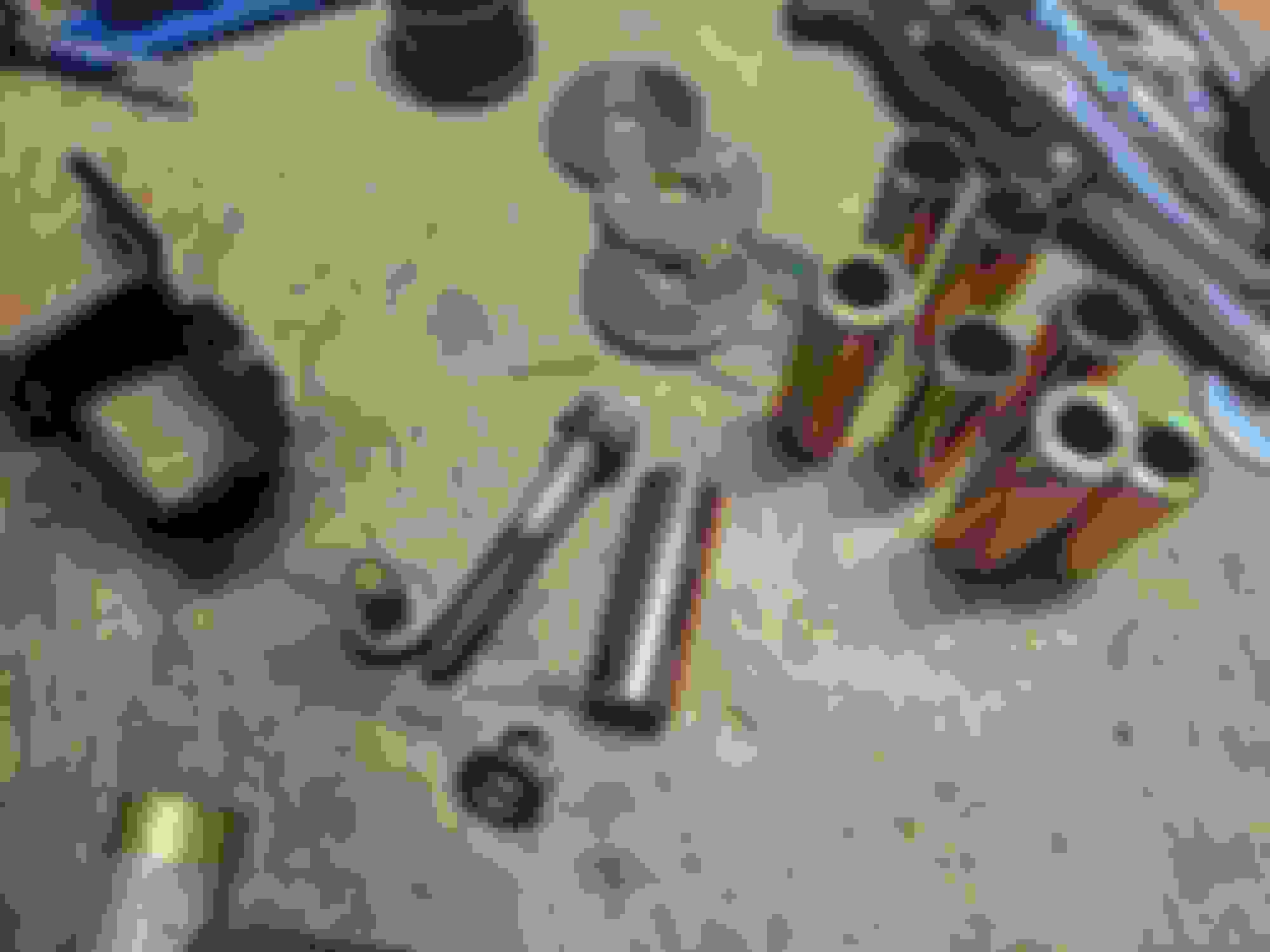
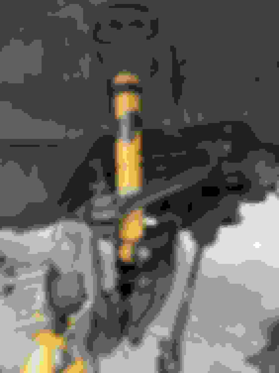
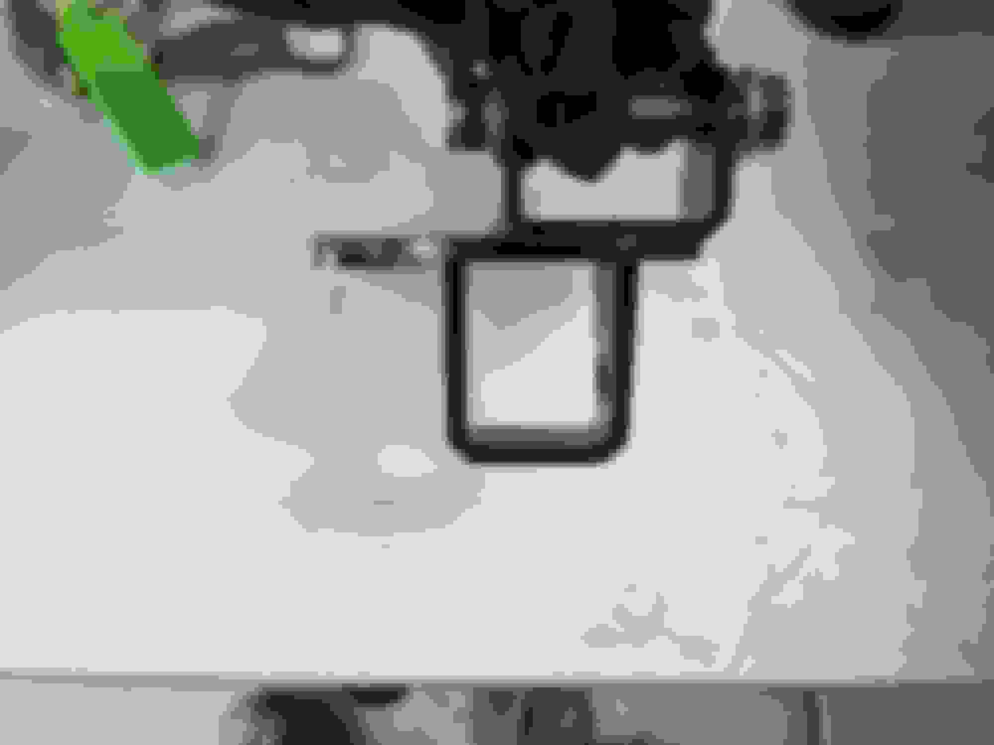
These yellow cad plated steel sleeves leftover from the Energy Suspension poly bushing kit seemed ideal
Damn, almost looks like they were designed for it. Now we just need to cut to length, and keep it square.
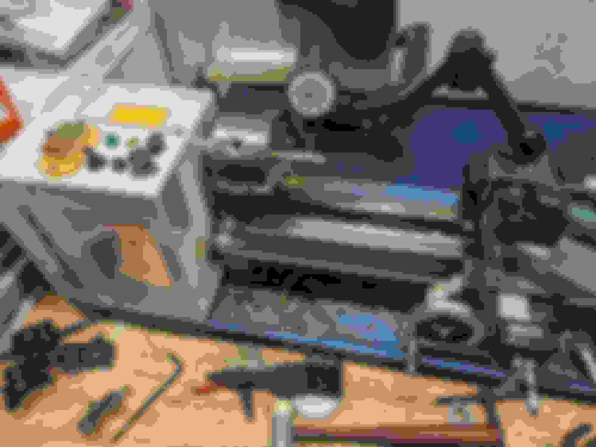
Quick! To the Mini Lathe!
Which of course had nowhere near the rigidity to handle parting this off, so I cut them close to length with the portaband (lol) and faced them down square in the lathe.
******' MINT! BESPOKE CRUSH SLEEVES!!!
I now have some level of confidence I'm not going to completely ratfuck the lower shock mounts and that the fasteners will maintain proper torque. This would be a fairly easy addition to the kit and would save a bunch of people destroying things, because you aren't going to be able to "easily go back to stock" if you've destroyed the shock mounting points.
Anyway, then I chucked this junk into the car.
Shock was installed without spring, seat or bump stop (the reasons for which will become apparent later) and everything was torqued to spec.
Here's another pisser... I'm about 80% sure the hardware that comes with the Paco kit is SAE because I'm reaching for metric sockets that I've never actually touched before. Someday I'll put some brain power into actually looking at them and figuring it out, otherwise for now its just an annoyance.
Also annoying, I forgot to reinstall my ELBJs, so this all had to come out and go back in again. ARGH.
Once its all installed, I'm not sure which part is actually limiting droop travel. The shock is a blonde one from contacting the FUCA:
The marks in the paint are from me brutalizing the shock into place. It's not full contact, but its close. I'll have to remove the FUCA and hit that with my purse just so I can sleep at night. I think the ELBJ binding internally may be limiting droop travel. Which is truly annoying. I'll have to take it apart and explore this in more detail later.
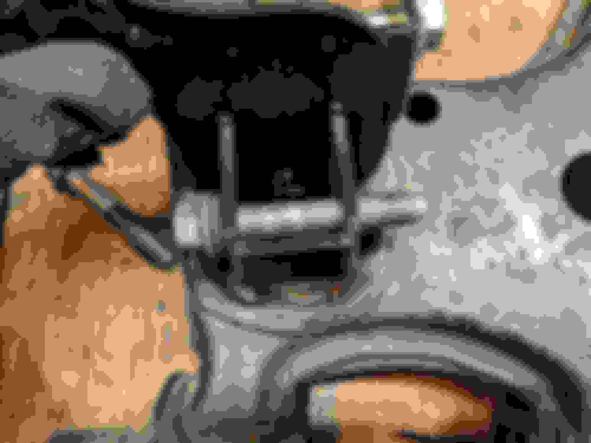
And speaking of annoyances, lets move to the rear. Here's the lift spacers installed in the RLCAs.
The "arm" with the eye in it going off toward the center of RLCA is also of particular annoyance. Its a clamp bolt that goes through the arm and the mount that clamps on... unsupported sheet metal in the center of the arm. Great. There's no torque spec on that, the FM instructions just say to "There isn�t a specific torque here, just �snug�. Don�t tighten it so much that you deform the sheet metal of the control arm." yeah, no ****. I'm basically at a loss as to what this fastener is actually doing, because the hole in the RLCA that it drops through is significantly larger than the bolt. The only thing I can think of is maybe to keep the mount from rotating, but if this mount starts to rotate we're going to have MUCH bigger problems, ones that a "snug" M8 bolt installed with "hotdog down a hallway" fitment through sheet metal arm is not going to solve. I guess the parts count needed to be higher? Gotta pump up that BOM, gotta justify the price
Moving on, again we have the same problem with the shock mount bolt, so we'll use the same solution that I pioneered on the FLCAs.
More mini lathe vs crush sleeve action....
And BAM! Steel support crush sleeve.
And following what we did in the front, we install the shock with no spring or bump stop, and torque everything to spec.
Now I don't know about you, but that doesn't look straight. At all. in the least.
This is especially evident in the lower shock bushing eye.
That bushing is not happy. That explains why the lower shock bolts were such a bastard to get through the eyes.
You remember my super fancy *** rear shock mounts with the spring locator ring? Well, I certainly did, and they made the problem quite evident.
So what the **** exactly is going on here?
Well, the Paco rear spacer isn't "straight up" like the front spacer. If you look at FM and Paco's websites, you'll notice there isn't really a side profile pic of the rear spacer.
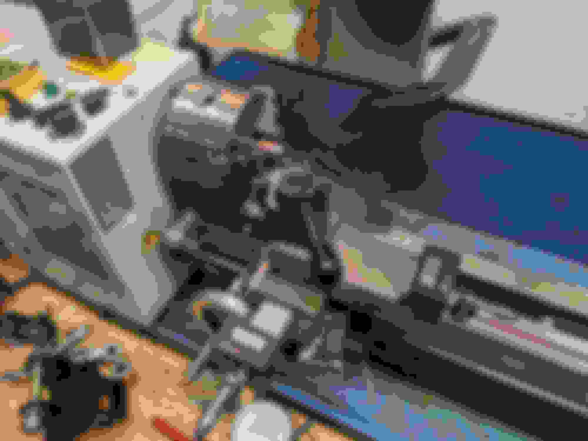
Well, here's a profile pic of the rear spacer after I completely ripped apart the rear suspension. AGAIN. To get these out and try to troubleshoot what the hell I could have actually done wrong.
And here's one where I get to show off my fancy steel crush sleeve bushing again
So "the ****" that is exactly going on here is Paco is pushing the shock mount about 13.5mm towards the rear of the car. Its "probably fine" with a stock top hat and bushings as they would take up that angle quite easily and unless you are really paying attention, you probably wouldn't notice it if you were installing a complete spring and shock assembly. Fortunately my fancy custom top hat is the only reason I noticed. Which is awesome.
Well this is stupid, why would they do this?
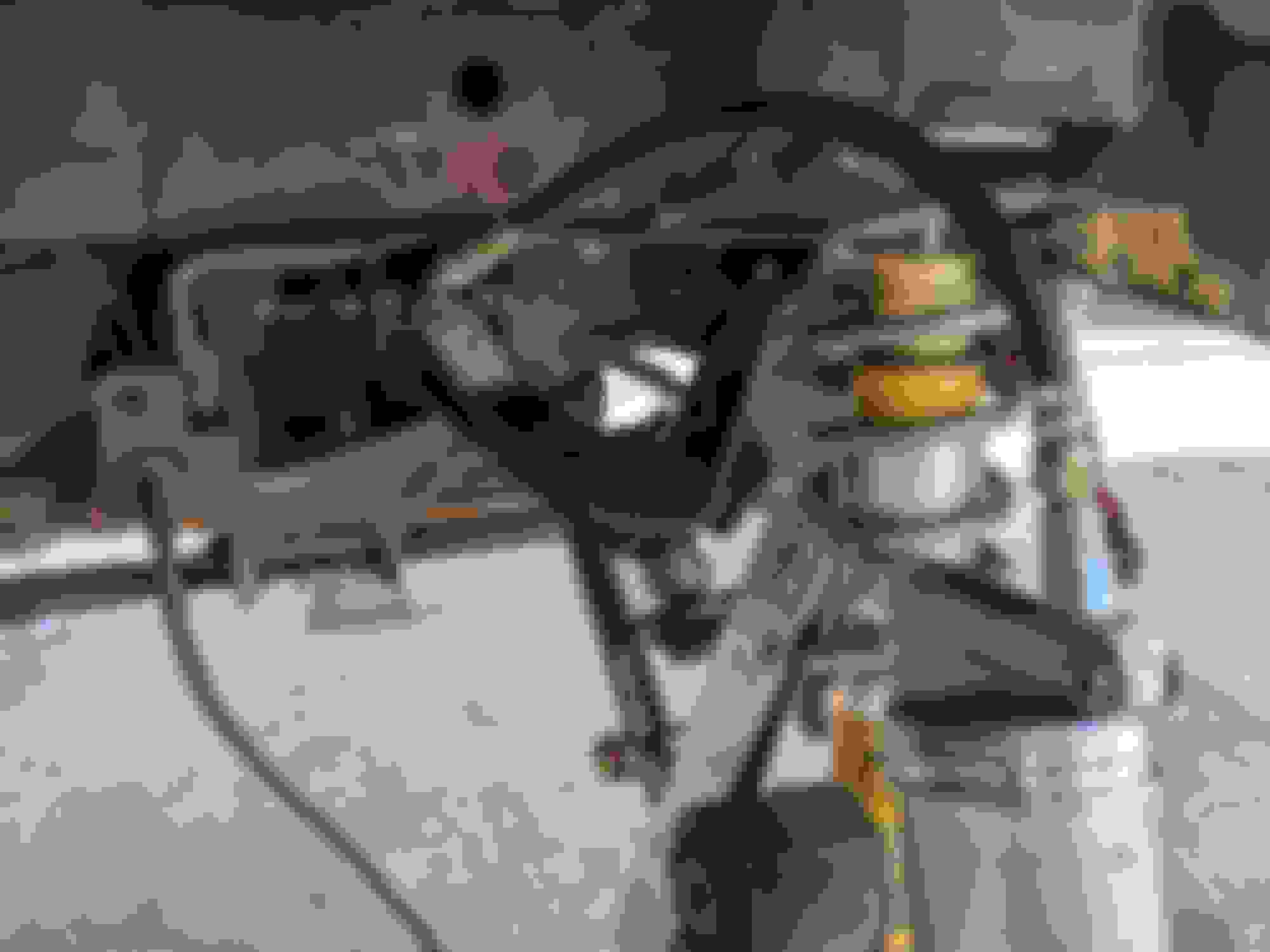
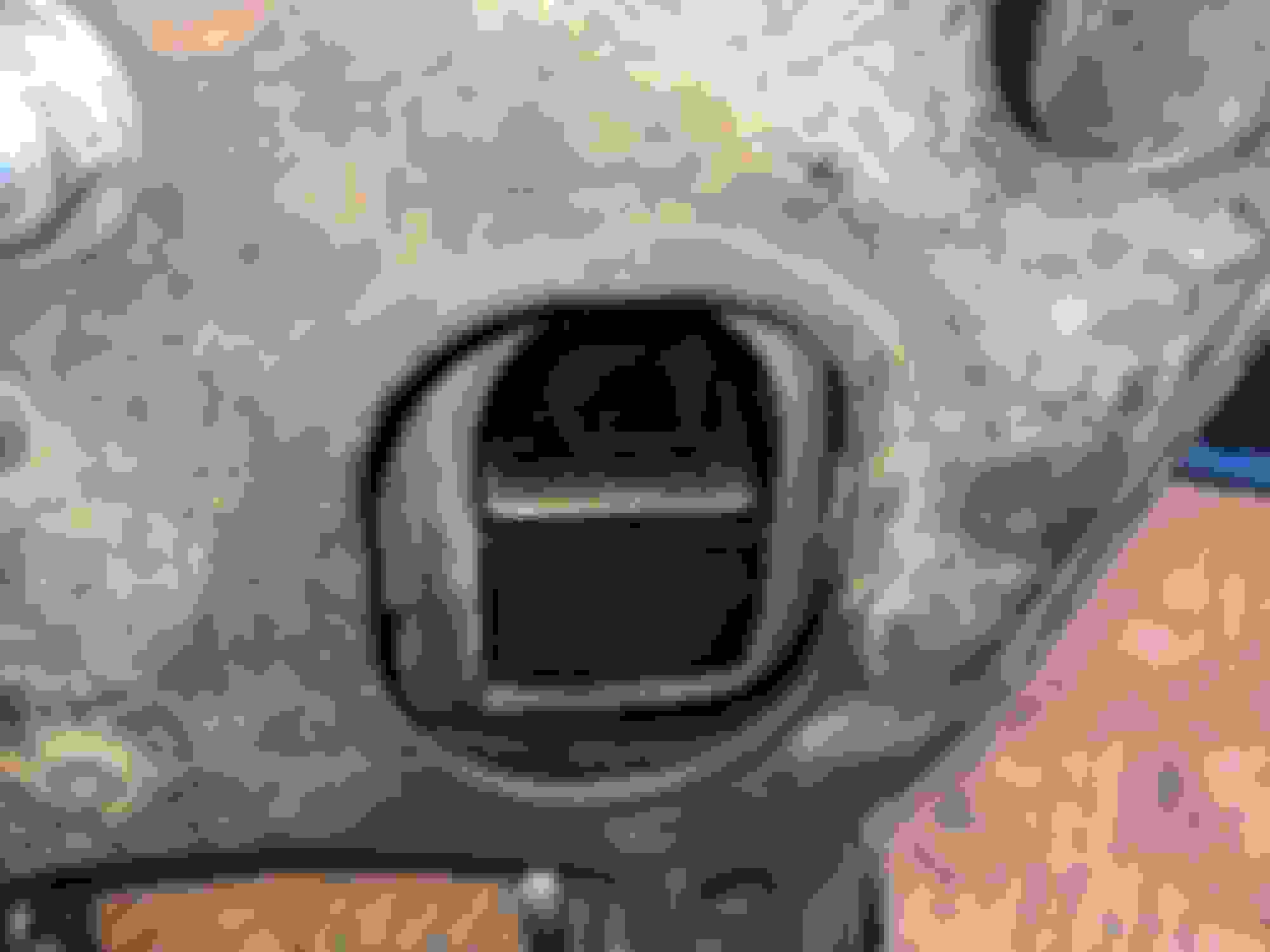
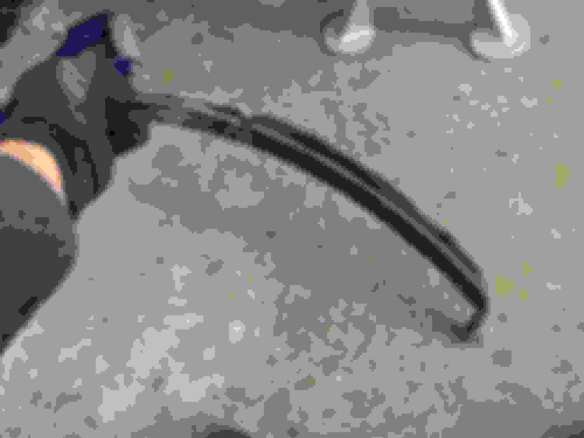
The only thing I can come up with is that they are trying to clear the CV boot at the axle. At full droop with the CV distended, it looks like this:
At full droop you can't get the lower shock mount bolt installed from the axle side, so it has to come in from the rear (giggidy) and they wanted to make sure there was clearance for the CV. There is plenty of clearance for the CV. In fact, the clearance only gets better the further away you get from full droop. If I had to guess, and this is only a guess, this offset was probably driven by the choice of fastener, which is of course too long, and fatty nylock, and forced to be installed from the wrong side. I suspect you could get a socket head cap screw past the axle fairly easily with a minimum amount of suspension compression, but for now, short of stripping the powder coat, cutting the mount apart and then welding it back together, there is literally nothing I can do about this right now. The Miata suspension already has travel challenges in the rear, and I want as much as I can get, so the decision was made to pull the Maruha Motors extended NB top hats off the front and move them to the rear, and try to ignore the weird angle issue. I don't know how long those lower shock bushings are going to last (according to the part numbers these yellow Bilsteins are OE from a 99/00 "Sport" or 10AE) but being that they are already 20 years old, I'll check them frequently and replace when it transitions from "mildly concerning" to "full blown problem."
I'll shoot an email to Paco eventually with these pics, I'll let y'all know how they reply.
Brad previously had a paco kit on, and well, I'll just say I wasn't happy with it. Was it fun having a lifted miata? Absolutely! Some of the most fun I've had in the snow. But ******* hell, everything was so wrong.
Heh. Yeaaaaaaah. I do think a couple of my clearance problems this time were due to nb rollerskate under na, but I know for sure there were problems last time. Not to mention the droop problems lol. I'm loving your write up. Keep it coming
Obviously you need shocks with spherical bushings to compensate for, well, a lot of things I guess. The offset on those doesn't make a whole lot of sense, at all. Hopefully Mark (Paco) will have some insight.
So with this aggressive of a tire package, some things are going to need to be cut. I figured it's good practice whenever you do a suspension project to remove the spring and bump stop, reassemble, then do all your clearance testing without the bump stop as to represent a "worst case scenario" for suspension compression. If it'll clear without the stop, it'll clear with the stop.
We'll start in the rear.
At this point I'd post a pic of the wheel mounted in the rear before making the fender clearance cut, but unfortunately its physically impossible to install these tires with the stock rear fender. Hard contact on the leading edge of the fender opening indicated that's where I'd start my work. I'll admit that I've never done this before so I was a bit nervous. Safety glasses, respirator, gloves, ear protection were all used whenever the grinder was in service. I'd love to own a face shield for such jobs but thanks to COVID you can't really buy PPE of any sort right now, so I opted to just hold my head to the side and hope for the best.
I made some quick measurements on the backside of the fender and then eyefucked a line on the front edge with a paint pen where I'd be working, then out came the cut off wheel.
Determination was made to start on the passenger side so that if I fucked it up, I wouldn't have to look at my mistakes every time I get in the car.
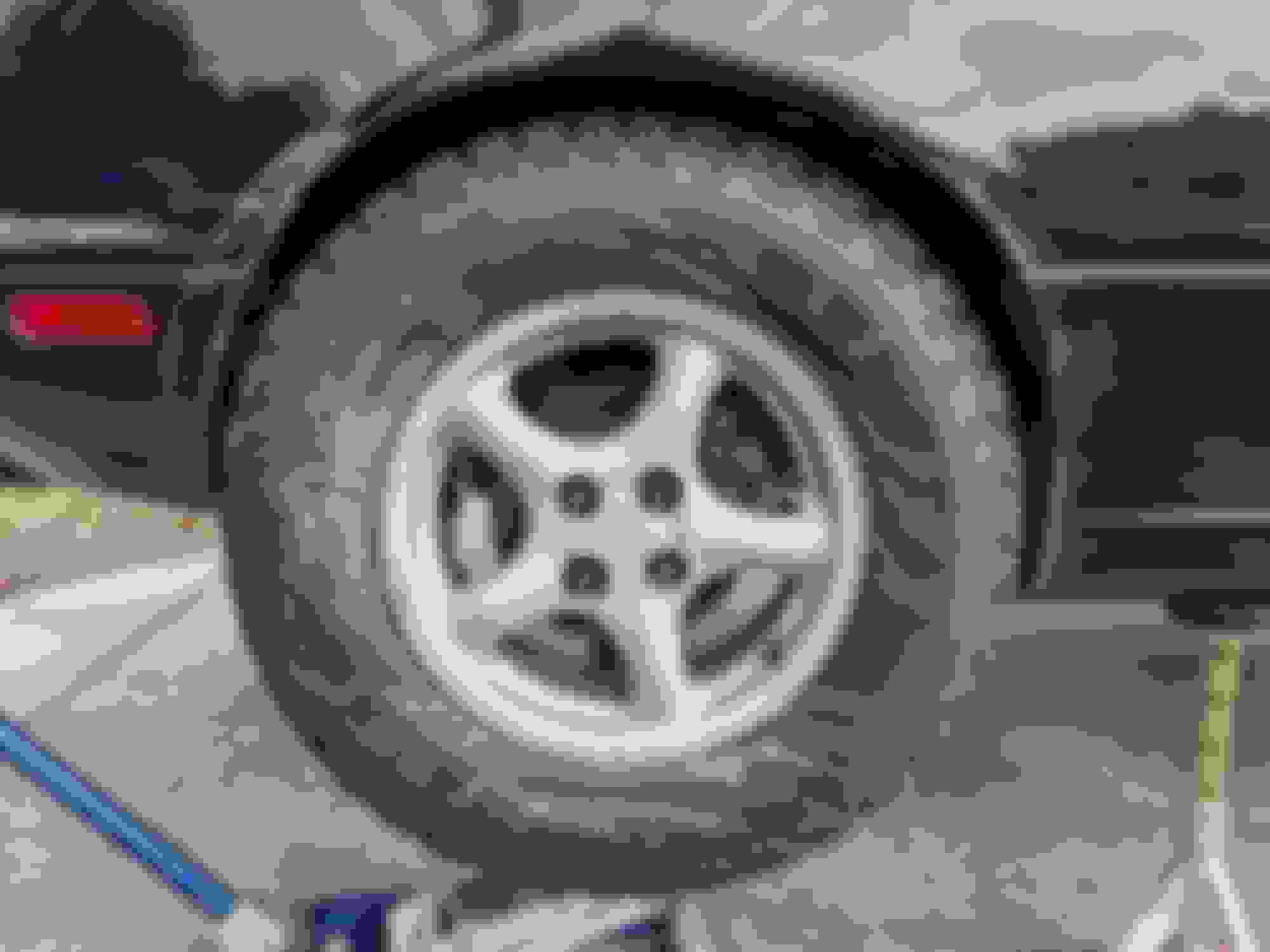
I'm usually out here working on this stuff alone in the driveway so I didn't bother taking pics or video of me taking a cut off wheel to the fenders, but it was quite spectacular. Hitting the pockets of bondo was my favorite part. #TeamRed M18 Fuel Grinder is a beast, lets me **** things up with a quickness.
For my first time cutting on a car, that looks pretty damn good. I assure you that the cut is straight and vertical, its the angle of the camera plus radius in the rear quarter and the roundness of the tire that makes it looked curved. I think this shot is the suspension at full compression, shock fully bottomed out with no bump stop, 20mm extended top hat but camber is not yet set. Regardless, I think I did pretty well. If you want to see full droop, go up a few posts. Good news is that full droop is limited by the shock hitting full extension, and I think that might be OK? Someone feel free to correct me if this is actually bad.
Actually, on second thought don't correct me because there isn't a whole lot I can do about it, other than maybe limiting straps. And that sounds annoying.
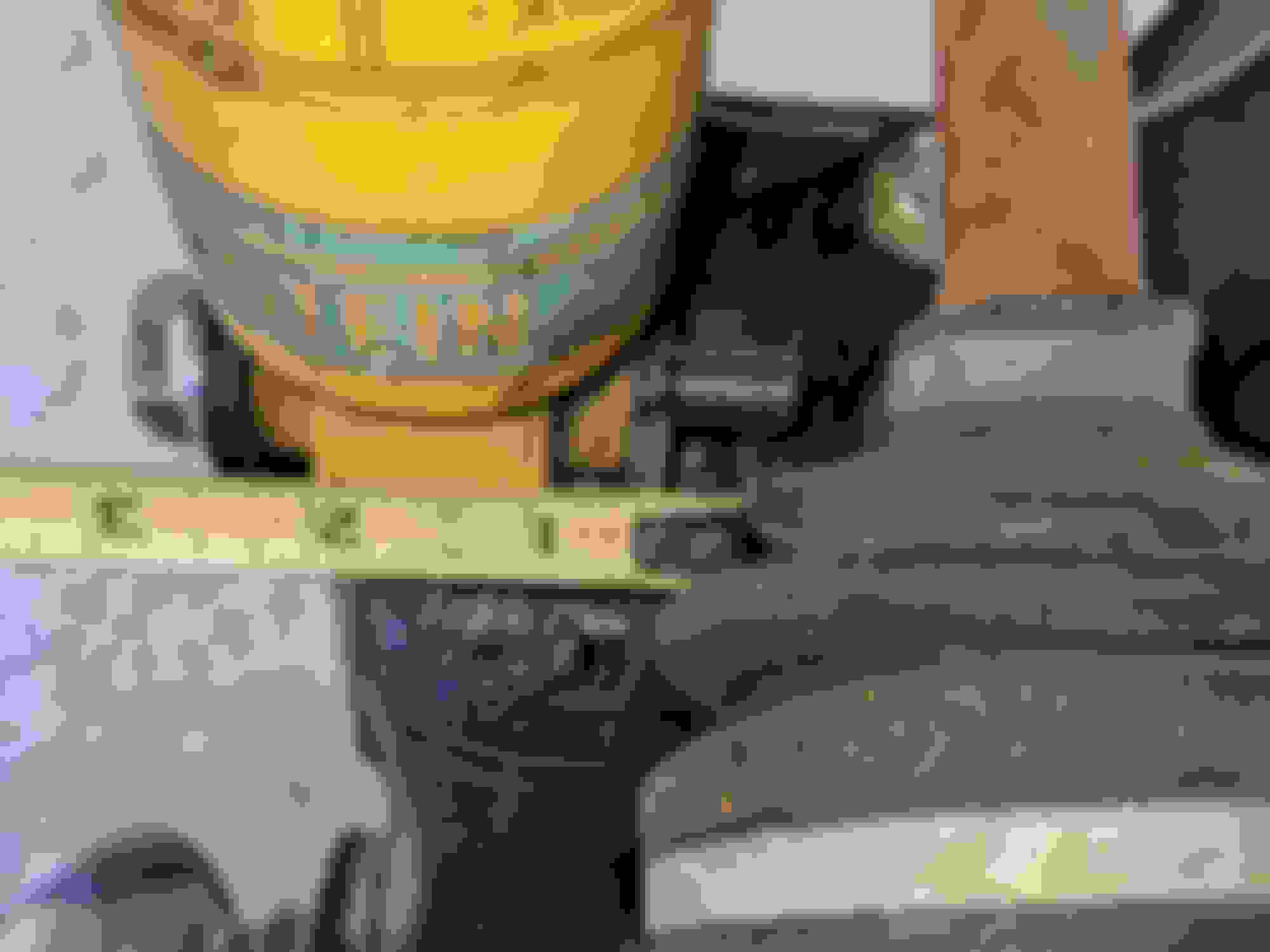
Thumb gauge says good2go
Tape measure agrees. I think slightly over 1" of clearance at the tightest point is completely reasonable. I might end up sneaking a little more out of it, and doing a bit of a radius at the bottom of the leading edge.
Note to self: do not sideload cheap Hazard Fraught cutoff wheels, lol.
You can see on that very bottom section where I can cut off that whole corner and give that a nice, smooth radius. Above that, I tried to make the cut in such a way that it would maximize tire clearance, but also leave enough of the "radius" in the inner fender apron piece of sheet metal so that it could be pinched back together with a pair of vice grips and then welded back up. Paint is gonna get rekt but that's OK, I have a great paint match for this car. I'd hazard that the seam, lip and welds that I cut off during this process probably add some level of rigidity to the arch so I'll feel much more comfortable when this is welded closed again.
As I famously do not posses a welder, this will need to wait until I can make arrangements with a friend to stop by and throw some lightning at it.
This process was of course repeated on the driver side.
I didn't take any pics, but at full droop there is the very real possibility of the sidewall, or at least the edge of the tread, making contact with edge of the "tube" feature in the body that the rear shock mounts into. The 15mm spacer is helping with this, as will my future camber adjustment. Right now its got a bit of negative camber, so the further that is adjusted out the better things are going to get. I've got enough fender clearance in the rear arch that even with extreme positive camber, I'm not going to have contact issues. Sweet!
I need to sit down with @Scaxx one of these days and figure out if the 7" 550/350 QA1 springs I've got installed are going to block before I hit the stops, but I fear he's going to try to make me measure things and do math, so I'll defer this issue as well.
So the rear is basically "done" minus the additional trimming I want to do at the bottom of the wheel well and a bit of welding to keep the wheel wells from coming apart, then paint to make it less ugly. Hells yes!
The more travel I have in the front, the more clearance issues I'll have to resolve. With this in mind, I opted NOT to install the super extendo hats from the rear, and instead dug around in the garage of plenty and pulled out the stock Showas that I removed from the NB back in 2011, and promptly stole the top hats.
Now Dear Readers, I am not a moron. Or at least, I claim not to be a moron. But the top hats haven't been off this suspension since they were installed by a Japanese robot in Hiroshima back in 1999 which means I've never taken apart a stock Miata shock assembly, so I have a solid excuse for the following. The pic above was taken approximately 20 seconds before I launched my M18 Fuel Impact directly into my groin with spring pressure from said assembly. It turns out that these are installed in compression, and blasting the nut off the top will cause it to explosively disassemble. Who knew? Certainly not this reporter.
After recovering from my unfortunate injury, this is what my test fit looks like for the front tire. Based on the sequence of pictures I found on my phone, I think this is full compression, but I'm not 100% sure it that's with the Maruha extended NB top hat, or the stock NB top hat. Either way I made the first clearance cut on the fender, and then determined the fender was the least of my worries. We know its gonna get butchered so might as well save that for later rather than fight it now. So the fender came off.
Again, with no spring and bump stop I placed a jack under the FLCA and ran it up to full compression on the shock
And now we get a better idea as to the extent of our clearance issues. And believe me, they are numerous.
Contact with the trailing edge of the plastic nose at the front of the wheel well is evident, as is contact with the steel body seam at the rear edge of the wheel well. The plastic nose is not a concern at the moment, plastic cuts easily and I can just pull it out of the way (though I will be disappointed to mess up my excellent paintwork.) The positive news here is that we don't have so much travel that we have to worry about contact anywhere else in the arch. w00t!
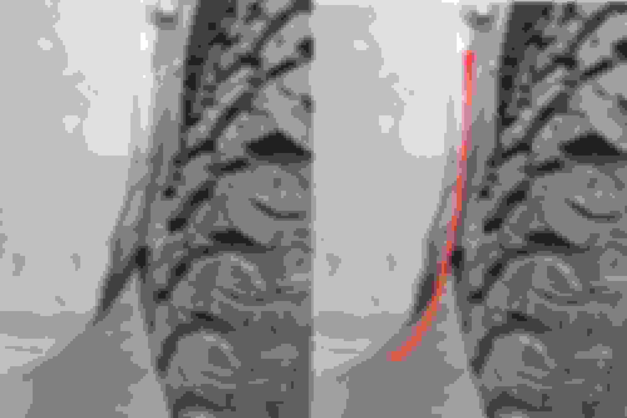
Unfortunately for us, front wheels must turn. I then hooked up the OTRE, unlocked the steering column and gave the wheel a shove.
At full droop we have clearance, which is great!
But with compression, it jams the wheel into the firewall. Hard. I'm going to have to to extensive work to get clearance here, and I'm not sure how I want to do it.
The raised and welded "seam" in the wheel well is clearly going to have to go. Red line indicates the cut.
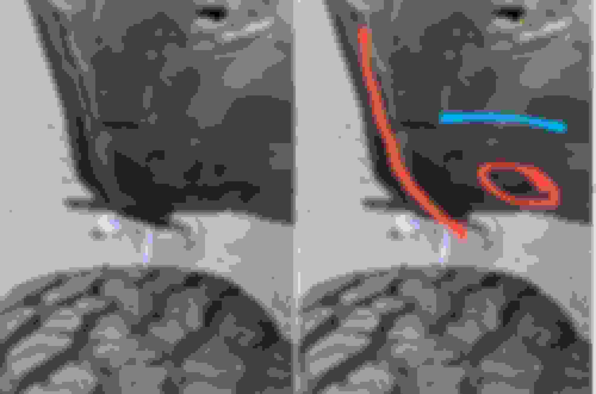
From another perspective. Big vertical red line is the previously mentioned slice, red circle is a contact point, and the blue triangle is the big "**** you" in here.
Here it is again from a slightly different angle. Bonus points for the blue highlight as I believe there is a diagonal support structure behind that sheet metal, perhaps extending into the cabin? I'll have to do some lookin'
I have not yet resolved this clearance issue. This is where I stopped because it started drizzling, and figured I post this up and get some opinions.
I've got enough hard contact here that I'm not sure just hitting it with a BFH is going to resolve the issue. I'm not against hitting it with the BFH, but right now its an order of operations challenge. The seam is most likely a 3 piece sheet metal lamination, similar to what we see on the lower part of the rear fender. Here's what I'm thinking my options are at this point:
I can hammer the clearance into the firewall for the wheel and then hammer what's left of the seam flat, and hope there is still enough material there to stretch.
If I cut the raised seam out and then start wailing on the firewall with the hammer, it will undoubtedly open up the seam making it very difficult to close again. And by close I mean scab a piece of steel in there with the welder.
If I don't make the cut, it may "pull" the seam in making it nearly impossible to cut up later, though that'll make it easier to hit with a hammer?
One thing I absolutely do not want to do is leave any sharp edges sticking out of the firewall/fender interface that can cut into the tire, in any situation. If I was a professional and had any ability to fabricate anything, a plasma cutter and a sheet of steel would magically appear in this location granting me tremendous clearance, but as I have neither the tools, skills or space to make that happen... its not going to happen. I'd pay someone in beer to do it, but I don't have a billion dollars to pay a shop to fab something.
Anyway, that's kinda where I'm at. I figured y'all would appreciate the updates as to what I've been up to for the past week or so
Today, EO2K learned why spring compressors are a thing which exists.
Glad you weren't seriously injured. In all seriousness, pretty much all OEM struts / coilovers are assembled in compression. And there's some pent-up mechanical anger in that spring.
 12-30-2020, 05:49 PM


 3
3


 Not sure why you have any interested in my pile of garbage but thanks for stopping by!