My First Turbo build!

 01-21-2017, 12:22 AM
#63
Junior Member

Join Date: Jan 2016
Posts: 452
Total Cats: 21
You just literally need to open a new project and hit detect, the project will be detected and tunerstudios will select the corresponding firmware. Serial mismatch happens when TS believes its one firmware and the ECU is running a different firmware


Reply
 0
0

0
 01-23-2017, 07:24 PM
#67
Junior Member
Join Date: Jan 2016
Posts: 452
Total Cats: 21
Shoot, I forgot you need some stupid adapter file to reflash hi-res onto ms1. You can try this one https://www.miataturbo.net/megasquir...windows-52140/
I had no luck with that one, I had to use some file I found on an old m.net thread, I'll see what I can dig up.
Like people said before, now would be time for a reflash.
EDIT: https://forum.miata.net/vb/showthread.php?p=4349770 post #20
I had no luck with that one, I had to use some file I found on an old m.net thread, I'll see what I can dig up.
Like people said before, now would be time for a reflash.
EDIT: https://forum.miata.net/vb/showthread.php?p=4349770 post #20
Reply
0
0
01-31-2017, 08:45 AM
#68
Junior Member
Thread Starter

Join Date: Dec 2016
Location: Commerce, Ga
Posts: 155
Total Cats: -1

So about to make my first order of everything except the PCB. I am going to build the harness adapter first while I have the money for that then I can purchase the other one in a few weeks. My question is, why the two harnesses? It doesn't really specifiy in the article what the megasquirt bundle is for. Just the MS3x bundle. Do you splice them together in the end or what? Thanks.
Reply
0
0
01-31-2017, 09:51 AM
#69
mkturbo.com


iTrader: (24)
Join Date: May 2006
Location: Charleston SC
Posts: 15,188
Total Cats: 1,684
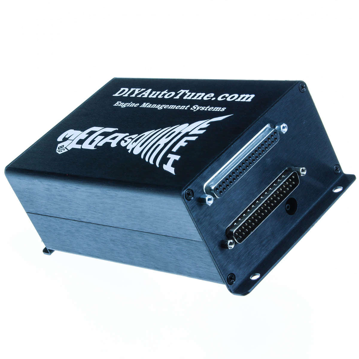
When you build an MS3X there are 2 DB37 connectors on it. The top db37 is for the expander board and you use the 3X wiring bundle for it. The bottom db37 is for the megasquirt wiring bundle. You will run wires from both db37's over to the connector that you plug into the stock harness.
Reply
0
0
01-31-2017, 09:54 AM
#70
Junior Member
Thread Starter
Join Date: Dec 2016
Location: Commerce, Ga
Posts: 155
Total Cats: -1
When you build an MS3X there are 2 DB37 connectors on it. The top db37 is for the expander board and you use the 3X wiring bundle for it. The bottom db37 is for the megasquirt wiring bundle. You will run wires from both db37's over to the connector that you plug into the stock harness.
Reply
0
0
02-03-2017, 10:01 AM
#73
Junior Member
Thread Starter
Join Date: Dec 2016
Location: Commerce, Ga
Posts: 155
Total Cats: -1

Reply
0
0
02-03-2017, 10:20 AM
#74
Boost Czar
iTrader: (62)
Join Date: May 2005
Location: Chantilly, VA
Posts: 79,607
Total Cats: 4,102
R52 is a variable resistor, but we always tune it to be at 100K ohms. So instead, I use a spare 100K ohm resistor, R22, and install it in the R52 position instead (outer two holes).
R13/R19. We don't install R13, but the left hole of R13 goes to 5v. The right hole of R45 is part of the VR input circuit. Bridging the left hole of R13 to the right hole of R45, via a 1K resistor (R19), provides the necessary pull-up for that circuit.
R13/R19. We don't install R13, but the left hole of R13 goes to 5v. The right hole of R45 is part of the VR input circuit. Bridging the left hole of R13 to the right hole of R45, via a 1K resistor (R19), provides the necessary pull-up for that circuit.
Reply
0
0
02-03-2017, 10:21 AM
#75
Junior Member
Thread Starter
Join Date: Dec 2016
Location: Commerce, Ga
Posts: 155
Total Cats: -1
R52 is a variable resistor, but we always tune it to be at 100K ohms. So instead, I use a spare 100K ohm resistor, R22, and install it in the R52 position instead (outer two holes).
R13/R19. We don't install R13, but the left hole of R13 goes to 5v. The right hole of R45 is part of the VR input circuit. Bridging the left hole of R13 to the right hole of R45, via a 1K resistor (R19), provides the necessary pull-up for that circuit.
R13/R19. We don't install R13, but the left hole of R13 goes to 5v. The right hole of R45 is part of the VR input circuit. Bridging the left hole of R13 to the right hole of R45, via a 1K resistor (R19), provides the necessary pull-up for that circuit.
Reply
0
0
02-03-2017, 09:00 PM
#76
Junior Member
Thread Starter
Join Date: Dec 2016
Location: Commerce, Ga
Posts: 155
Total Cats: -1


So for $200 I got a STIM built, and a MS3 kit with the board kinda done. Unfortunately I have to do the things I talked about before that they didn't do. But it was a surprise.
Reply
0
0
 02-06-2017, 09:22 PM
#80
Junior Member
Thread Starter
Join Date: Dec 2016
Location: Commerce, Ga
Posts: 155
Total Cats: -1


So there is the 99% done I'm pretty sure. The problem above and that one is the only thing I'm missing. But I'm taking a break for today. I loaded the firmware, the map sensor works, and reads correctly. Also do I need to jumper for the IAC and PWM? So I just need those 4 questions answered. And I can finish up the main board.
Last edited by ANONYMOUS_HAM; 02-07-2017 at 09:56 AM.
Reply
0
0


