Ian's 99 build thread
 12-23-2014, 03:02 AM
#81
Elite Member

Thread Starter
Join Date: Mar 2007
Location: Santa Clara, CA
Posts: 5,178
Total Cats: 858
I had to clock my compressor outlet up at a 2 o'clock position to clear with the FM manifold and I still had to hammer the pinch weld down flat against the frame rail.
My FM cast mani had been relief cut by the previous owner. I still had to cut it two more times since then because it continues to close up over time. I also had it resurfaced (of course) because I knew the casting was gradually changing shape over time. It happens until it reaches its point of relaxation and stasis, I guess.
My FM cast mani had been relief cut by the previous owner. I still had to cut it two more times since then because it continues to close up over time. I also had it resurfaced (of course) because I knew the casting was gradually changing shape over time. It happens until it reaches its point of relaxation and stasis, I guess.
Fortunately, the 2863 compressor isn't all that big. The motor came out again this afternoon and I basically doubled the length of the bent-over portion of the lip on the "shelf". It fits nicely now.
The motor is back in the car now, and I've got about half the various bits hooked up to it. I discovered that even though the Skunk2 throttle body claims to be interchangeable with the stock one, it's actually 1/4 inch larger diameter on the outside so the standard FM silicone elbow doesn't fit. Argh. Fortunately, that's not a complex piece, and a 2.75 to 2.5 reducer elbow from siliconeintakes.com should fix it.
--Ian

Reply
 0
0

0
12-23-2014, 11:28 AM
#82
Elite Member
iTrader: (37)

Join Date: Apr 2010
Location: Very NorCal
Posts: 10,448
Total Cats: 1,900
The motor is back in the car now, and I've got about half the various bits hooked up to it. I discovered that even though the Skunk2 throttle body claims to be interchangeable with the stock one, it's actually 1/4 inch larger diameter on the outside so the standard FM silicone elbow doesn't fit. Argh. Fortunately, that's not a complex piece, and a 2.75 to 2.5 reducer elbow from siliconeintakes.com should fix it.
--Ian
--Ian

Reply
0
0
01-25-2015, 01:41 AM
#83
Elite Member
Thread Starter
Join Date: Mar 2007
Location: Santa Clara, CA
Posts: 5,178
Total Cats: 858
Man, has it really been a month since I posted anything on this thread? The holidays got in the way, then it was too freaking cold to work on the car, then I bruised my ribs and got sick and didn't feel like rolling around on the cold concrete floor.
OK, enough with the whining and excuses, how about some progress?
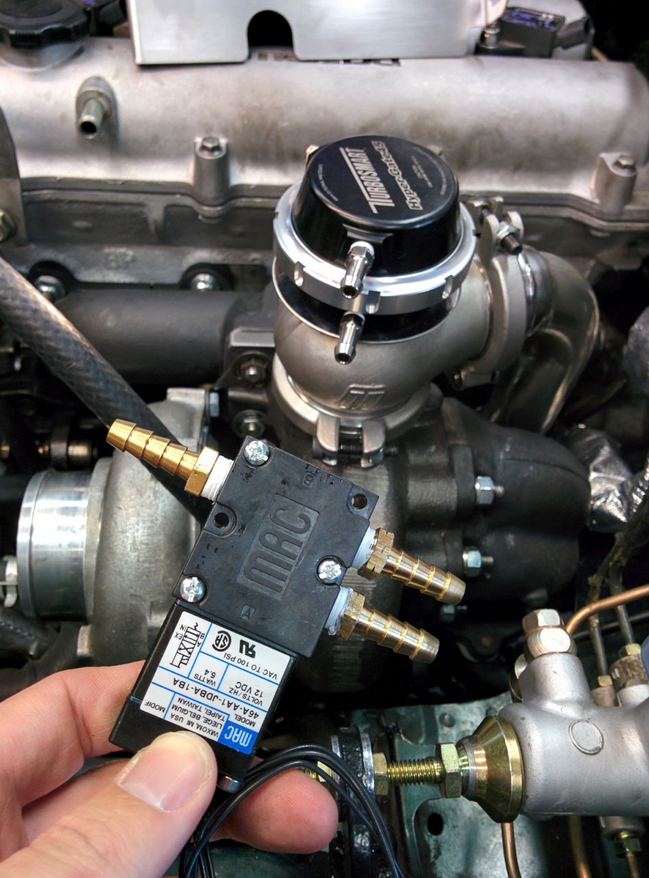
A while back I picked up a MAC dual-port boost control solenoid to use with the EWG on the FM2R.
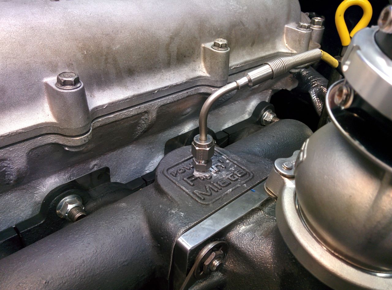
I also got the right compression fitting to install the Autometer EGT sender. The stupid thing came with a leaky fitting using a setscrew to hold it in, WTF?
So today I put in the oil cooler (no photos), buttoned up a bunch of other little stuff, and started working on the intake. My goal is to keep most of the FM2 intake, but the Skunk2 throttle body is larger than stock (2.75" vs 2.5") and the inlet on the GTX2863R is 3" instead of the 2.5" on the GT2560, so some changes were required.
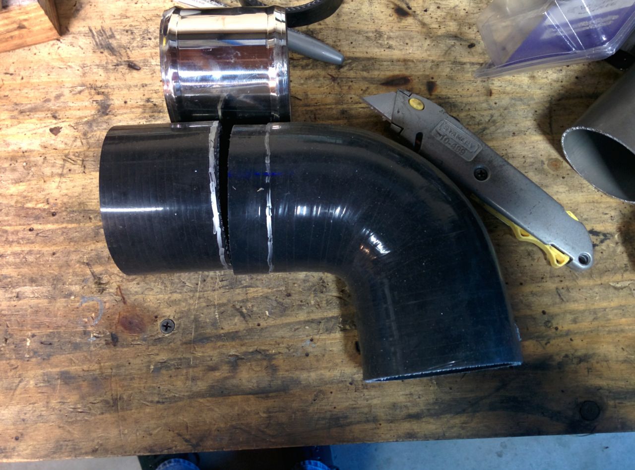
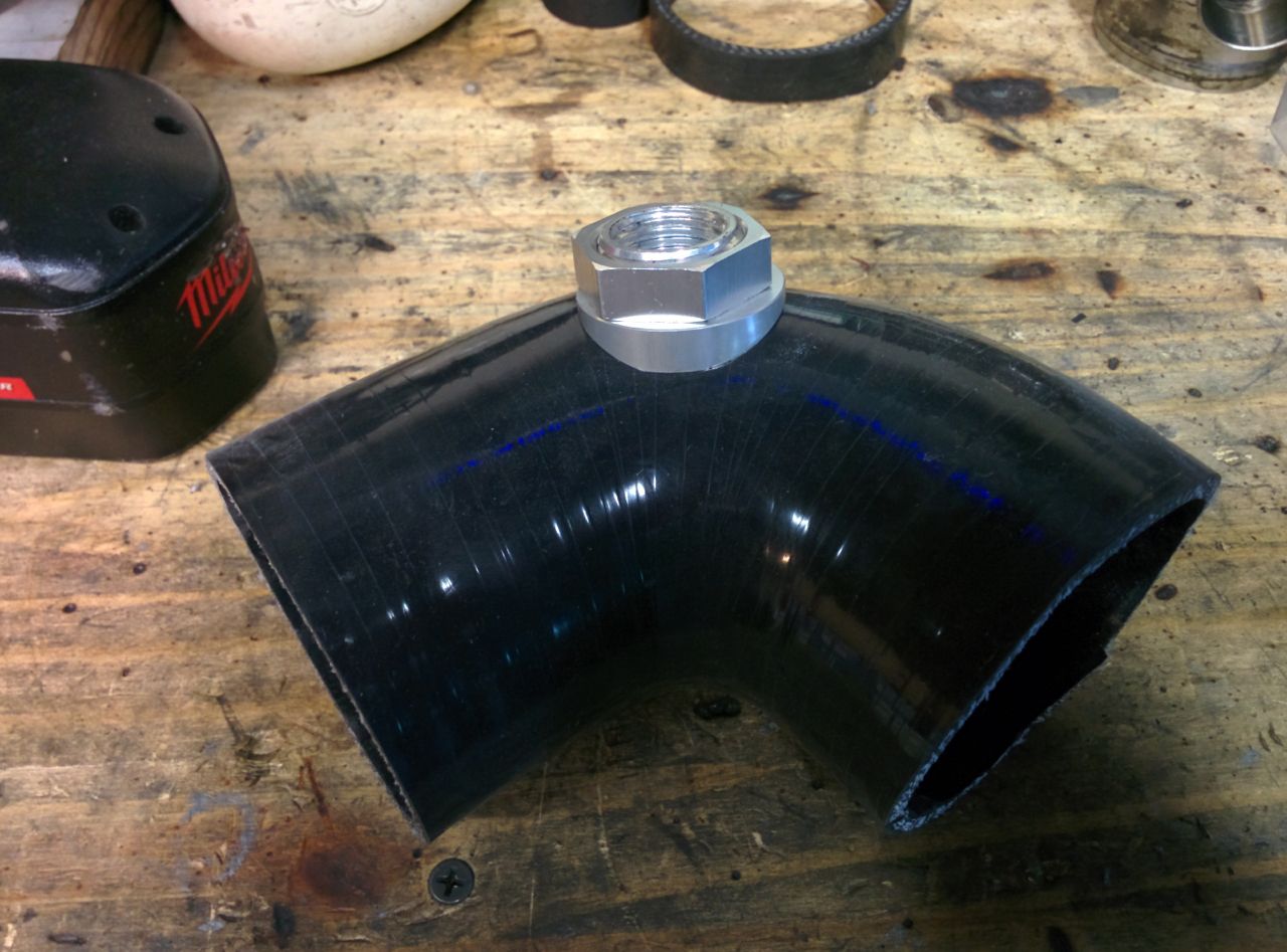
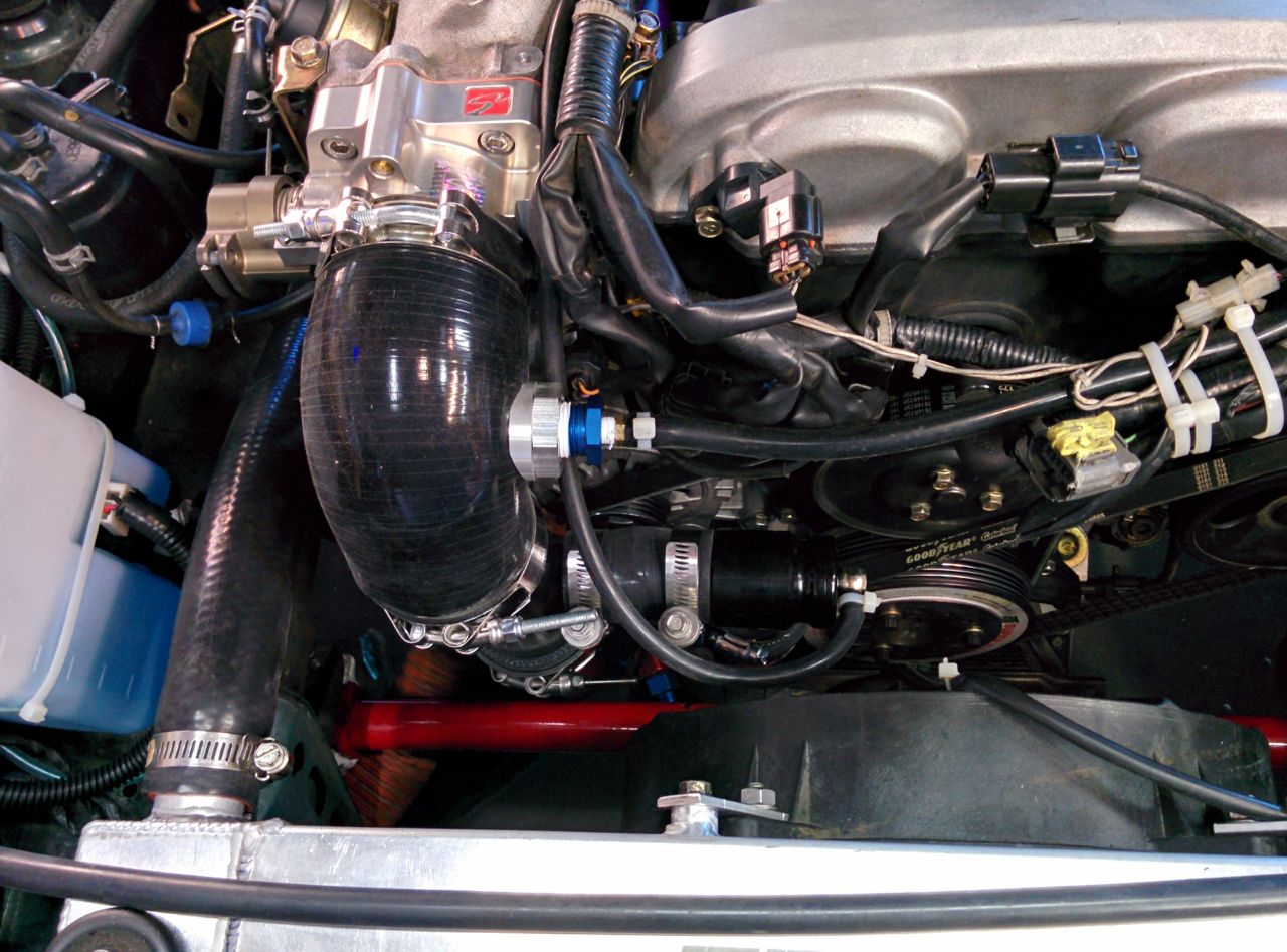
For the compressor inlet, the FM2 comes with a molded silicone 90 degree elbow, 2.5" on one end and 2.75" on the other. It's longer on the 2.5" side, and has 2 ports in it for the cam breather and bypass valve recirc. I want to keep the filter & MAF delete pipe from the FM2, so I bought a 2.75" to 3" reducing elbow from siliconeintakes.com. That's not quite long enough on the 3" side, so a short length of coupler extends it, but the 3" coupler is a teeny bit TOO long. Cutting 0.75" off each of the elbow and the coupler makes it work.
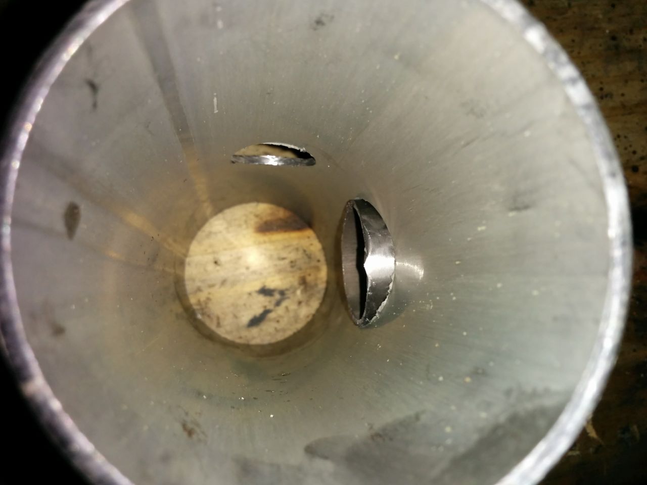
Next I needed a port for the cam breather, doing this using the port adapters that siliconeintakes also sells. Hole saw makes a hole in the elbow:
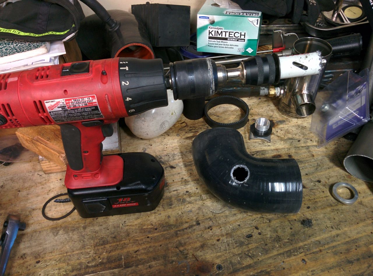
And then you get a 1/2" NPT port mounted in the hole.
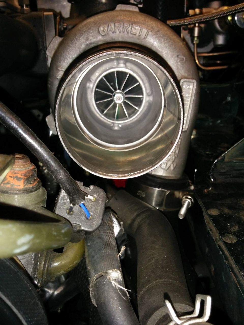
A look down the turbo inlet...
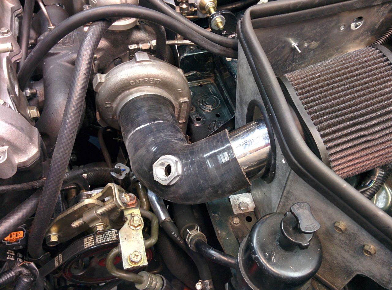
And it's all attached. I need some bigger hose clamps to secure it, though.
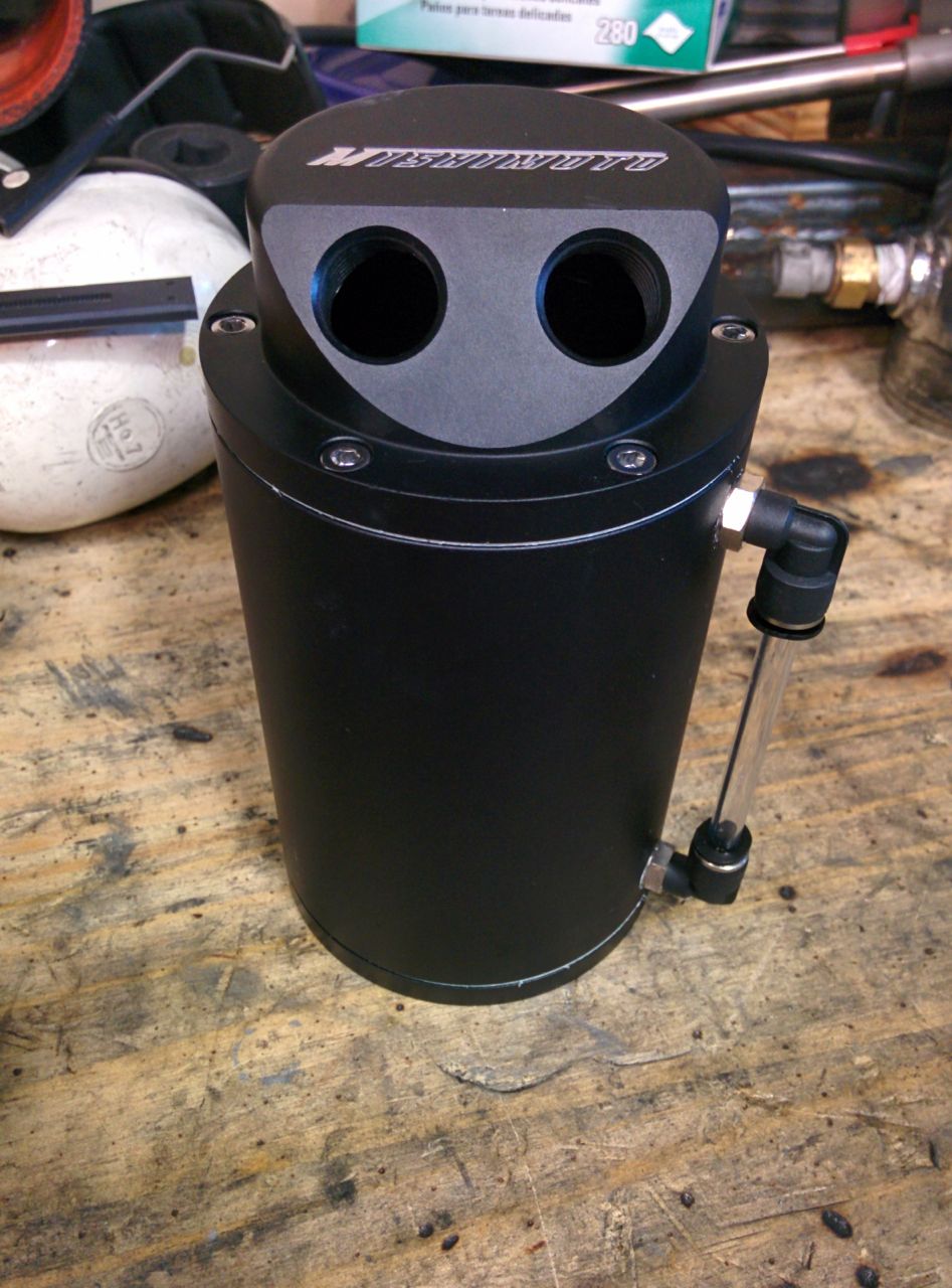
I also picked up a catch can to put between the breather and the intake. Not installed yet, though.
The throttle body requires some work too, because it's now 2.75" instead of 2.5". I have an older FM2 kit which has a long molded silicone pipe from the intercooler outlet to a short stainless pipe, then a short elbow from the pipe to the throttle body. The stainless pipe has the air temp sensor and the bypass valve attached to it. This is a good thing, becasue the elbow that's now the wrong size is a fairly simple piece. Once again I went to siliconeintakes and got a reducing elbow (2.75" to 2.5" this time), but, once again, it was slightly too short. You *can* attach it to the car, but it's putting a lot of strain on the compressor outlet pipe and wants to pop off. Argh. That stainless pipe could really do with being about 2 inches longer.
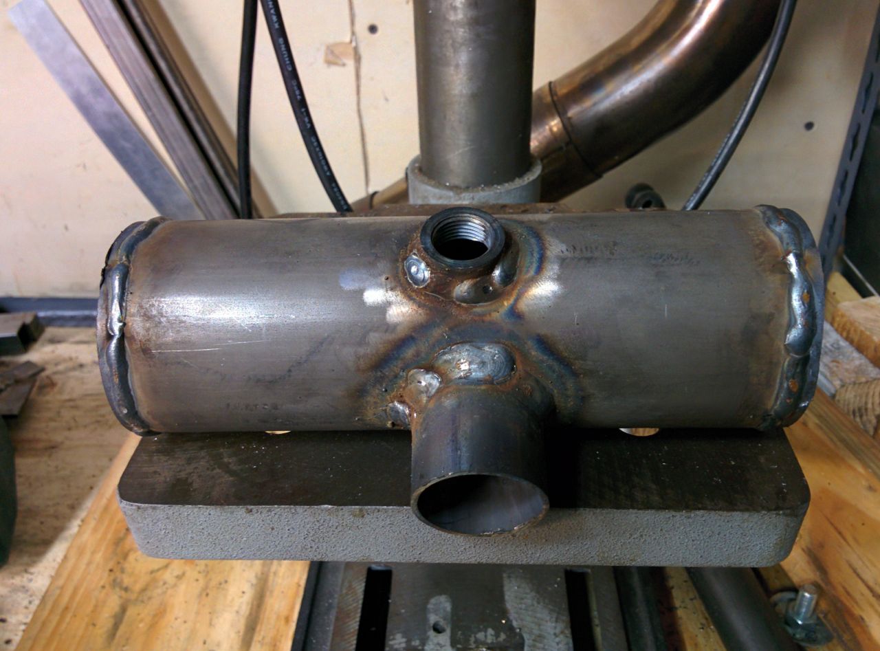
I bought a mig welder about a year ago, so I decided to take a crack and making a replacement pipe. (I don't want to try welding an extension on the FM stainless piece, so I'm making the whole thing). My welding skills are weak though, so I used some fairly thick-wall tubing.
Two holes, one for the bypass valve, one for the AIT sensor.
Will need to grind this out when it's done.
I suck at welding.
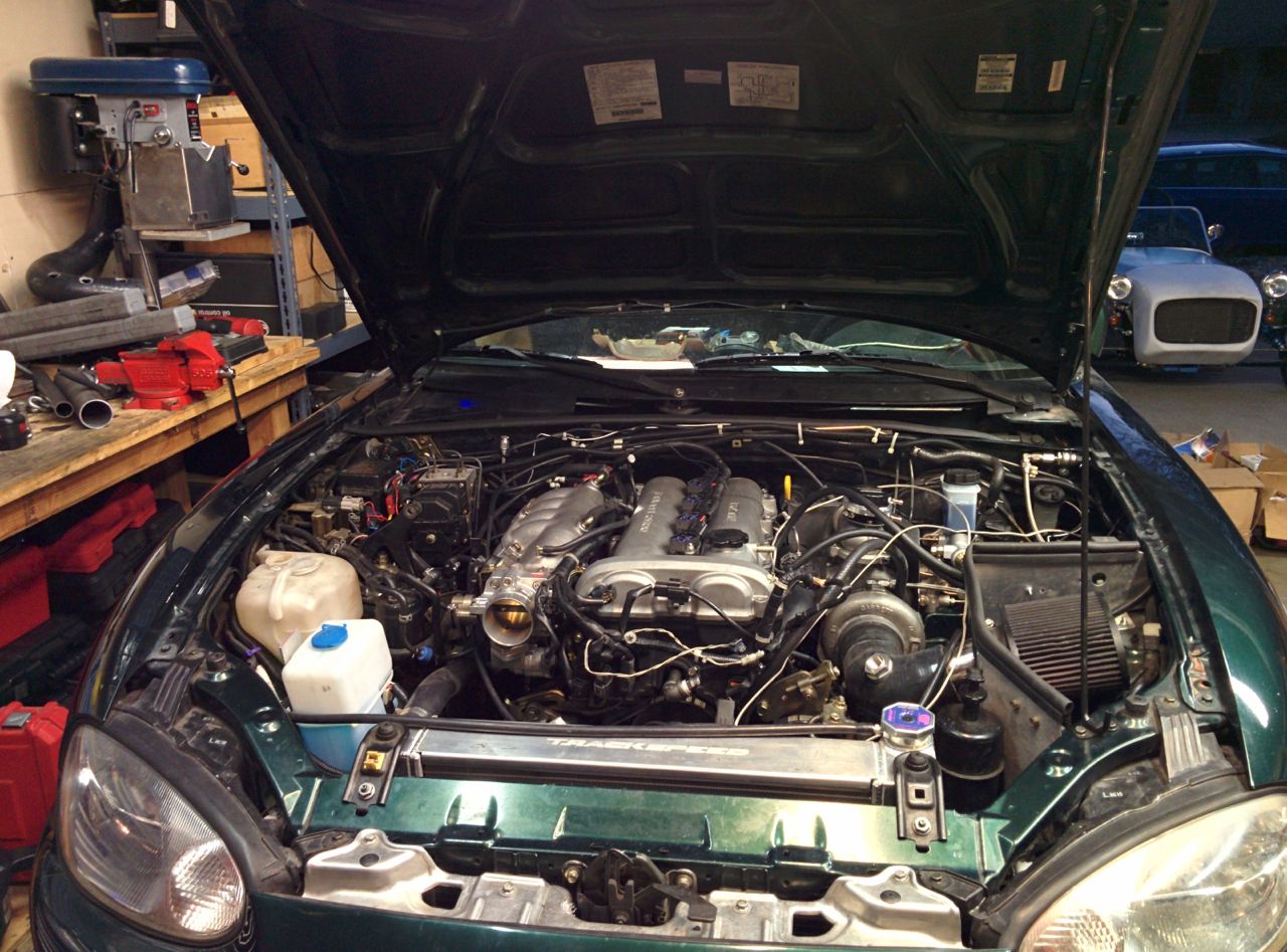
Here's the car as it sits now. Need to paint and install the new pipe -- not much left to do after that before trying to start it!
--Ian
OK, enough with the whining and excuses, how about some progress?
A while back I picked up a MAC dual-port boost control solenoid to use with the EWG on the FM2R.
I also got the right compression fitting to install the Autometer EGT sender. The stupid thing came with a leaky fitting using a setscrew to hold it in, WTF?
So today I put in the oil cooler (no photos), buttoned up a bunch of other little stuff, and started working on the intake. My goal is to keep most of the FM2 intake, but the Skunk2 throttle body is larger than stock (2.75" vs 2.5") and the inlet on the GTX2863R is 3" instead of the 2.5" on the GT2560, so some changes were required.
For the compressor inlet, the FM2 comes with a molded silicone 90 degree elbow, 2.5" on one end and 2.75" on the other. It's longer on the 2.5" side, and has 2 ports in it for the cam breather and bypass valve recirc. I want to keep the filter & MAF delete pipe from the FM2, so I bought a 2.75" to 3" reducing elbow from siliconeintakes.com. That's not quite long enough on the 3" side, so a short length of coupler extends it, but the 3" coupler is a teeny bit TOO long. Cutting 0.75" off each of the elbow and the coupler makes it work.
Next I needed a port for the cam breather, doing this using the port adapters that siliconeintakes also sells. Hole saw makes a hole in the elbow:
And then you get a 1/2" NPT port mounted in the hole.
A look down the turbo inlet...
And it's all attached. I need some bigger hose clamps to secure it, though.
I also picked up a catch can to put between the breather and the intake. Not installed yet, though.
The throttle body requires some work too, because it's now 2.75" instead of 2.5". I have an older FM2 kit which has a long molded silicone pipe from the intercooler outlet to a short stainless pipe, then a short elbow from the pipe to the throttle body. The stainless pipe has the air temp sensor and the bypass valve attached to it. This is a good thing, becasue the elbow that's now the wrong size is a fairly simple piece. Once again I went to siliconeintakes and got a reducing elbow (2.75" to 2.5" this time), but, once again, it was slightly too short. You *can* attach it to the car, but it's putting a lot of strain on the compressor outlet pipe and wants to pop off. Argh. That stainless pipe could really do with being about 2 inches longer.
I bought a mig welder about a year ago, so I decided to take a crack and making a replacement pipe. (I don't want to try welding an extension on the FM stainless piece, so I'm making the whole thing). My welding skills are weak though, so I used some fairly thick-wall tubing.
Two holes, one for the bypass valve, one for the AIT sensor.
Will need to grind this out when it's done.
I suck at welding.
Here's the car as it sits now. Need to paint and install the new pipe -- not much left to do after that before trying to start it!
--Ian
Reply
0
0
01-25-2015, 01:52 AM
#84
Elite Member
iTrader: (37)
Join Date: Apr 2010
Location: Very NorCal
Posts: 10,448
Total Cats: 1,900
That's the same MAC solenoid I was looking at buying, just not sure if it works with my MS3 or not. No heatsoak from the IAT in that location?
Great progress! You certainly weld better than I do
Great progress! You certainly weld better than I do
Reply
0
0
 01-25-2015, 04:03 AM
#86
Elite Member
Thread Starter
Join Date: Mar 2007
Location: Santa Clara, CA
Posts: 5,178
Total Cats: 858

That's where FM puts the IAT sensor, and where it's been on my car for pretty much the entire time I've had a turbo on it, so I assume it's OK.
--Ian
Reply
0
0
01-25-2015, 06:46 PM
#88
Elite Member
Thread Starter
Join Date: Mar 2007
Location: Santa Clara, CA
Posts: 5,178
Total Cats: 858
--Ian
Reply
0
0
01-25-2015, 06:52 PM
#90
Elite Member
iTrader: (37)
Join Date: Apr 2010
Location: Very NorCal
Posts: 10,448
Total Cats: 1,900
Nice! I regret not buying ID1000s only because someday I might get E85 around here somewhere, and because I will be configuring FlexFuel on my car with the GM 13577394 sensor. For now I'll just keep telling myself to be happy with my FIC650s.
Did you get an MS3 Basic or one of the other MS3 based models?
Oh yeah, I know. Remember I went from a DIYPNP to an MS3 Basic, I know all about hearsoak  Of course, none of this is going to keep me from installing my IAT in my intercooler end talk or just past the outlet behind the nose.
Did you get an MS3 Basic or one of the other MS3 based models?
Of course, none of this is going to keep me from installing my IAT in my intercooler end talk or just past the outlet behind the nose.
Reply
0
0
01-25-2015, 06:58 PM
#91
Elite Member
Thread Starter
Join Date: Mar 2007
Location: Santa Clara, CA
Posts: 5,178
Total Cats: 858
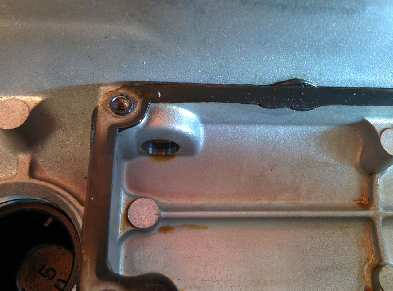
So the catch can that I bought has 9/16" hose barbs on it, which are way bigger than the roughly 3/8" hose barb on the VC. I had been planning on converting the catch can to use smaller barbs so as to use one size of hose for the whole breather, but from reading various threads on the topic it sounds like I'd be better off running the larger hose.
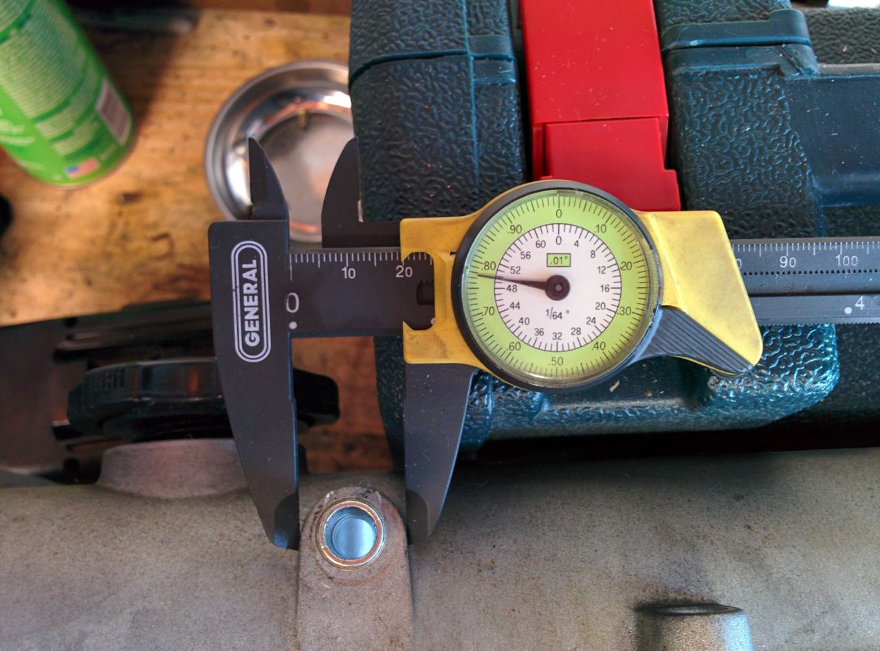
From reading various catch can threads, I see that various people have drilled the valve cover for larger fittings, so I pulled a spare valve cover apart to look at it. What size are people drilling it for? 3/8" NPT is how big the holes on the catch can are, but that's a 37/64" hole, and it really doesn't look like there's enough meat in the valve cover to drill it that big and then tap it. Any thoughts?
--Ian
Reply
0
0
01-25-2015, 07:04 PM
#92
Elite Member
Thread Starter
Join Date: Mar 2007
Location: Santa Clara, CA
Posts: 5,178
Total Cats: 858
Nice! I regret not buying ID1000s only because someday I might get E85 around here somewhere, and because I will be configuring FlexFuel on my car with the GM 13577394 sensor. For now I'll just keep telling myself to be happy with my FIC650s.
Did you get an MS3 Basic or one of the other MS3 based models?
Did you get an MS3 Basic or one of the other MS3 based models?
I believe it's an MSLabs (Reverant) MS3 Basic. The car ran great on it, except for the sync errors. The MS3 boost control is better than the (useless) Hydra 2.5 boost control, but nowhere close to as good as the GReddy Profec 2 Spec B standalone boost controller that I've been using. Fortunately the source is available for the MS3, so I can fix that.
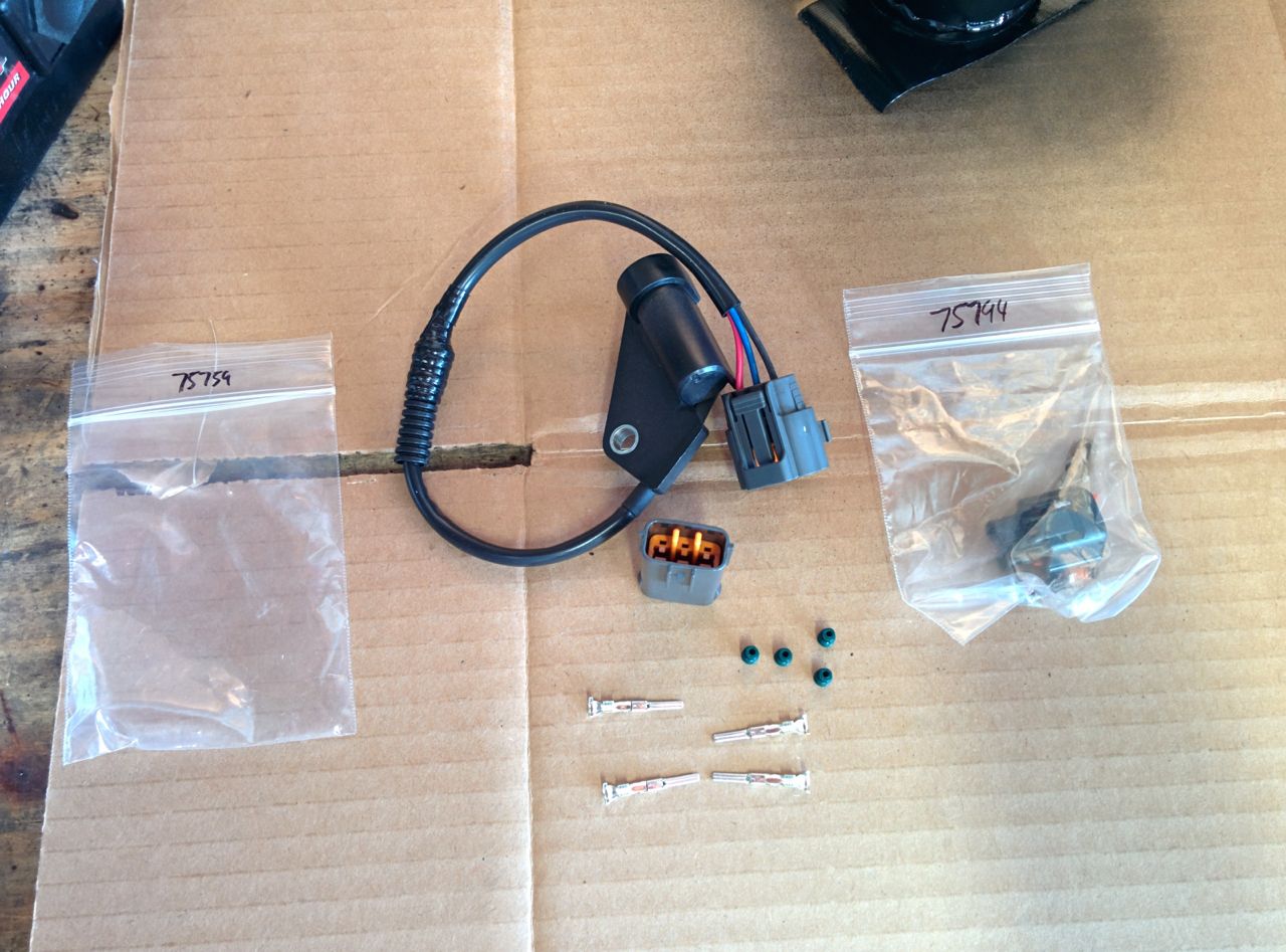
To fix the sync errors I picked up new cam & crank sensor connectors from Ballinger, and will be running shielded cable from the sensor all the way to the MS3. Jason's also going to do a bit of rework inside the MS3 to try to clean up the signal path.
--Ian
Reply
0
0
01-25-2015, 07:16 PM
#93
Elite Member
Thread Starter
Join Date: Mar 2007
Location: Santa Clara, CA
Posts: 5,178
Total Cats: 858
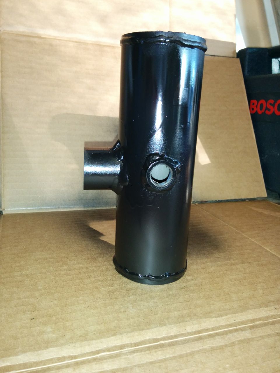
New pipe looking not-quite-as-ugly now that it's painted:
New OEM crank angle sensor and connectors from Ballenger:
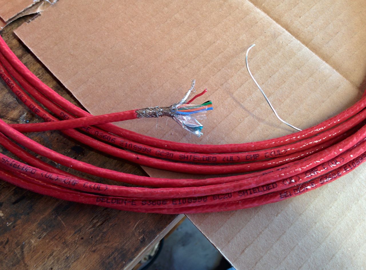
Surplus shielded cable from Halted. 6 conductor, foil and braided shield, teflon insulation, plenum rated, but relatively cheap due to being surplus.
--Ian
New OEM crank angle sensor and connectors from Ballenger:
Surplus shielded cable from Halted. 6 conductor, foil and braided shield, teflon insulation, plenum rated, but relatively cheap due to being surplus.
--Ian
Reply
0
0
01-25-2015, 08:07 PM
#94
Elite Member
iTrader: (37)
Join Date: Apr 2010
Location: Very NorCal
Posts: 10,448
Total Cats: 1,900
You are certainly not screwing around with the cabling. Do it once, do it right I guess.
I'm guessing thats form HSC Electric Supply in San Jose? Mind sharing a PN/SKU if you have it? I need some shielded cable like this for another project.
Reply
0
0
01-25-2015, 08:31 PM
#95
Elite Member
Thread Starter
Join Date: Mar 2007
Location: Santa Clara, CA
Posts: 5,178
Total Cats: 858
You are certainly not screwing around with the cabling. Do it once, do it right I guess.
I'm guessing thats form HSC Electric Supply in San Jose? Mind sharing a PN/SKU if you have it? I need some shielded cable like this for another project.
I'm guessing thats form HSC Electric Supply in San Jose? Mind sharing a PN/SKU if you have it? I need some shielded cable like this for another project.
Yes, it's from HSC. Huh, I thought this was the Sunnyvale location, but it turns out it's actually in Santa Clara. 3500 Ryder St, it's basically the intersection of Lawrence and Central.
This is from the surplus dept, there are no part numbers there. They get spools of cable from surplus sources and sell it by the foot, negotiating the price as they go along. It helps to bring cash. If you want some of this, I left the spool on the top shelf right above where it says "control cable".
--Ian
Reply
0
0
02-01-2015, 05:16 AM
#96
Elite Member
Thread Starter
Join Date: Mar 2007
Location: Santa Clara, CA
Posts: 5,178
Total Cats: 858
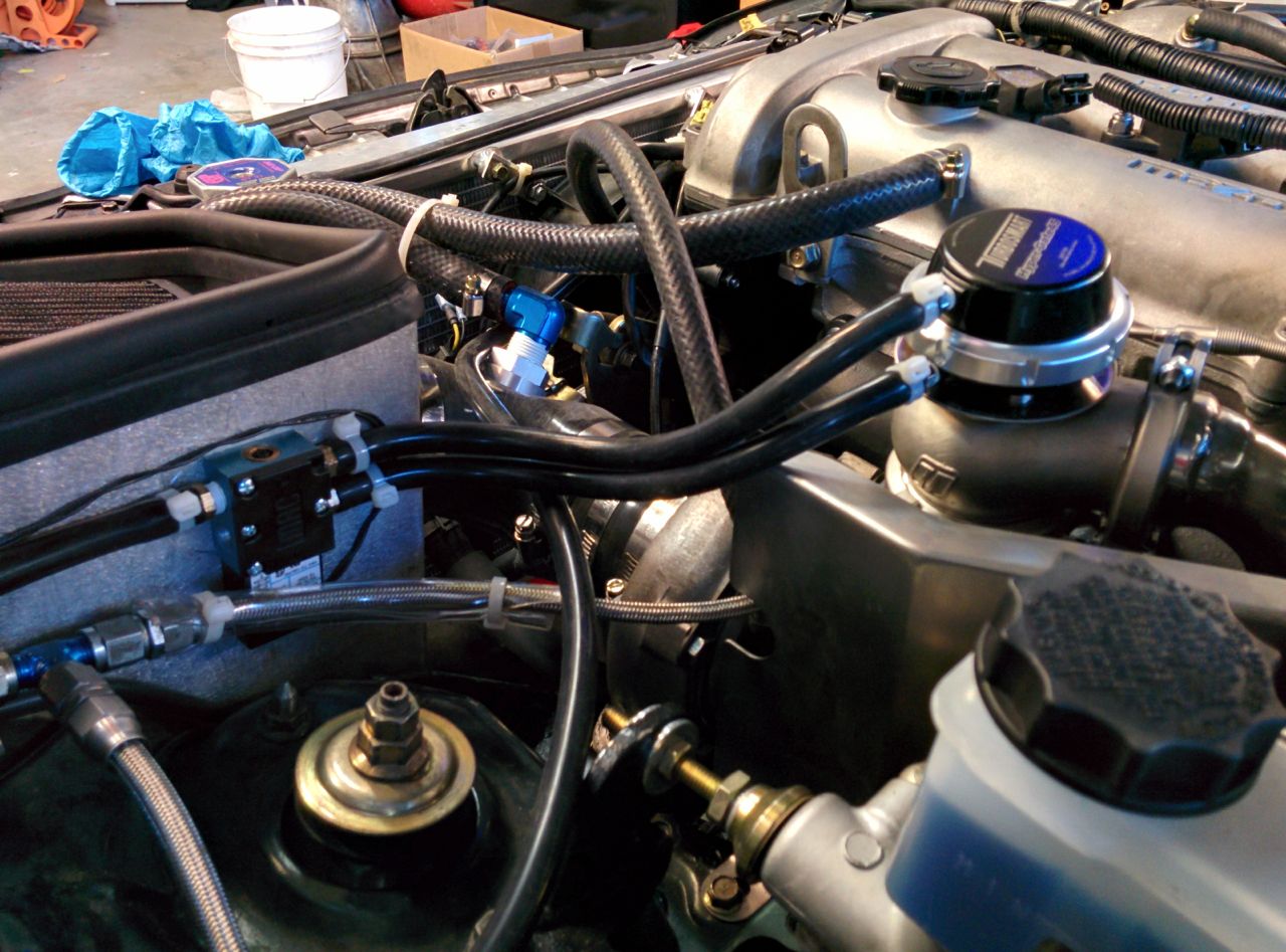
So I got the last few fittings I needed, and buttoned the intake together. Wastegate boost source is now coming from the inlet pipe to the throttle body:
The intake plumbed together, secured with hose clamps, and hooked to catch can. It's just using the factory hole in the valve cover for now:
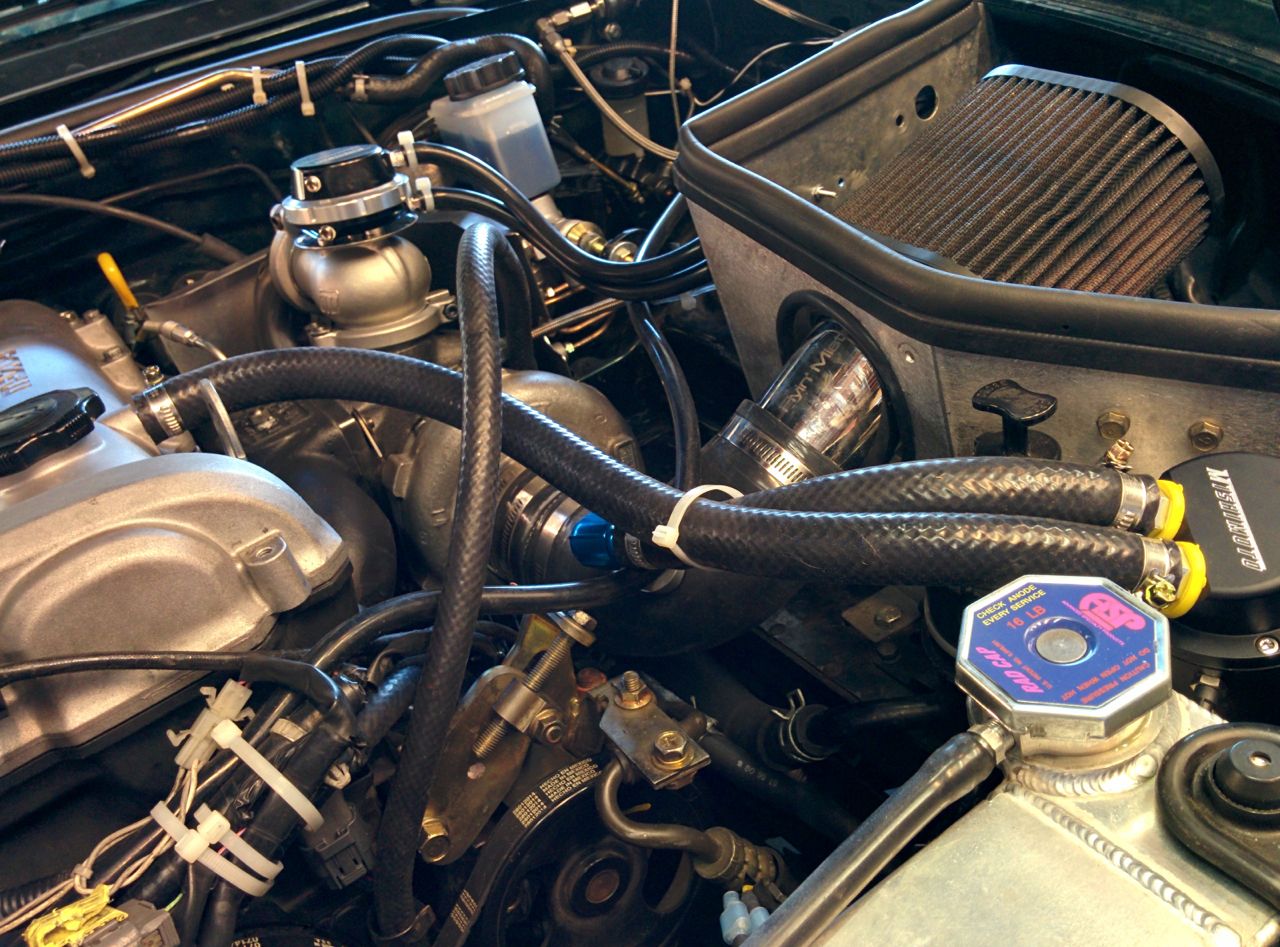
I hooked up the dual-port wastegate solenoid. Backwards. I didn't take another picture after fixing it, though. Too bad, because the hoses were all pretty this way.
And there it is, done. Well, not *done*, but ready to start and run.
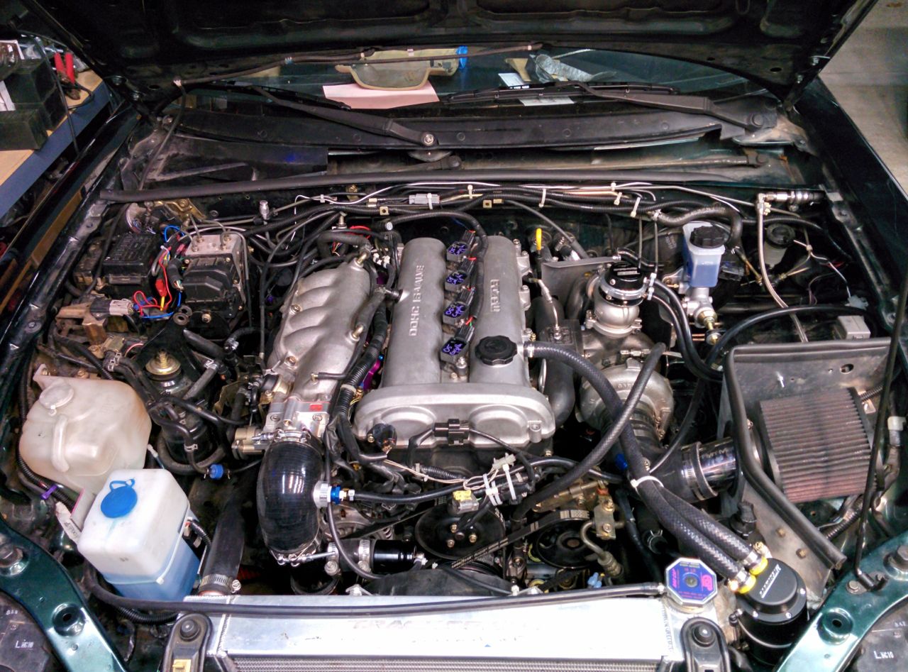
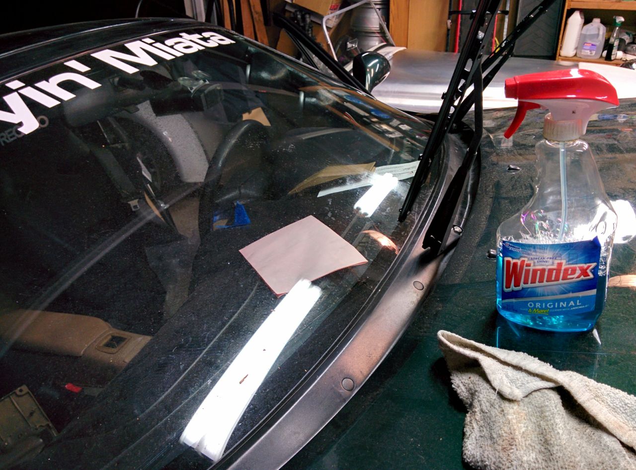
Time to clean the grime off the windows and set the tire pressures!
So, next steps were:
- pull the "fuel inj" fuse and crank til I got oil out of the turbo feed line. Then crank a bit more until I could see oil through the filler cap.
- Jack the front of the car WAY in the air to try to fill it with coolant.
- Replace a rubber fuel line that must've dried out from sitting for too long because it was leaking massively.
- Plug in the TPS and cam angle sensor. Oops.
And then it was time to crank it and try to start. Doh, battery is too low from cranking the oil, and it's not firing the spark properly. For whatever reason, aftermarket computers do *not* like starting my car whenever the battery is a bit low. The starter spins the engine fine, but they can't figure out when to fire stuff. The Hydra did it, the MS3 does it, but the factory ECU couldn't care less. Whatever, we stuck it on the charger and went to dinner.
After dinner it would crank and fire and immediately die. WTF, spent a while hunting that down before figuring out that the idle screw on the Skunk2 TB was screwed all the way in. Oops.
Fixed that and it started up and ran! Woohoo! But the wideband wasn't working, doh. Fortunately, that also turned out to be a not-quite-plugged-in-all-the-way sensor.
Took it out and did the FM break-in procedure. The new motor has 30 miles on it now, time to change the oil. The EWG that FM supplies appears to come with a 180 kpa spring in it -- looks like I need to order a smaller one if I want to take advantage of the dual-port wastegate.
--Ian
The intake plumbed together, secured with hose clamps, and hooked to catch can. It's just using the factory hole in the valve cover for now:
I hooked up the dual-port wastegate solenoid. Backwards. I didn't take another picture after fixing it, though. Too bad, because the hoses were all pretty this way.
And there it is, done. Well, not *done*, but ready to start and run.
Time to clean the grime off the windows and set the tire pressures!
So, next steps were:
- pull the "fuel inj" fuse and crank til I got oil out of the turbo feed line. Then crank a bit more until I could see oil through the filler cap.
- Jack the front of the car WAY in the air to try to fill it with coolant.
- Replace a rubber fuel line that must've dried out from sitting for too long because it was leaking massively.
- Plug in the TPS and cam angle sensor. Oops.
And then it was time to crank it and try to start. Doh, battery is too low from cranking the oil, and it's not firing the spark properly. For whatever reason, aftermarket computers do *not* like starting my car whenever the battery is a bit low. The starter spins the engine fine, but they can't figure out when to fire stuff. The Hydra did it, the MS3 does it, but the factory ECU couldn't care less. Whatever, we stuck it on the charger and went to dinner.
After dinner it would crank and fire and immediately die. WTF, spent a while hunting that down before figuring out that the idle screw on the Skunk2 TB was screwed all the way in. Oops.
Fixed that and it started up and ran! Woohoo! But the wideband wasn't working, doh. Fortunately, that also turned out to be a not-quite-plugged-in-all-the-way sensor.
Took it out and did the FM break-in procedure. The new motor has 30 miles on it now, time to change the oil. The EWG that FM supplies appears to come with a 180 kpa spring in it -- looks like I need to order a smaller one if I want to take advantage of the dual-port wastegate.
--Ian
Reply
0
0
02-01-2015, 05:19 AM
#97
Elite Member
Thread Starter
Join Date: Mar 2007
Location: Santa Clara, CA
Posts: 5,178
Total Cats: 858
Not all is smiles, though. The MS3 is back to its summer-time behavior of sending a sync error every 15-20 minutes of driving, and the new clutch is chattering. Argh. Need to put in the new cable for the sensor and probably pull the MS3 apart and rework the signal path a bit.
--Ian
--Ian
Reply
0
0
02-15-2015, 12:33 PM
#98
Elite Member
Thread Starter
Join Date: Mar 2007
Location: Santa Clara, CA
Posts: 5,178
Total Cats: 858
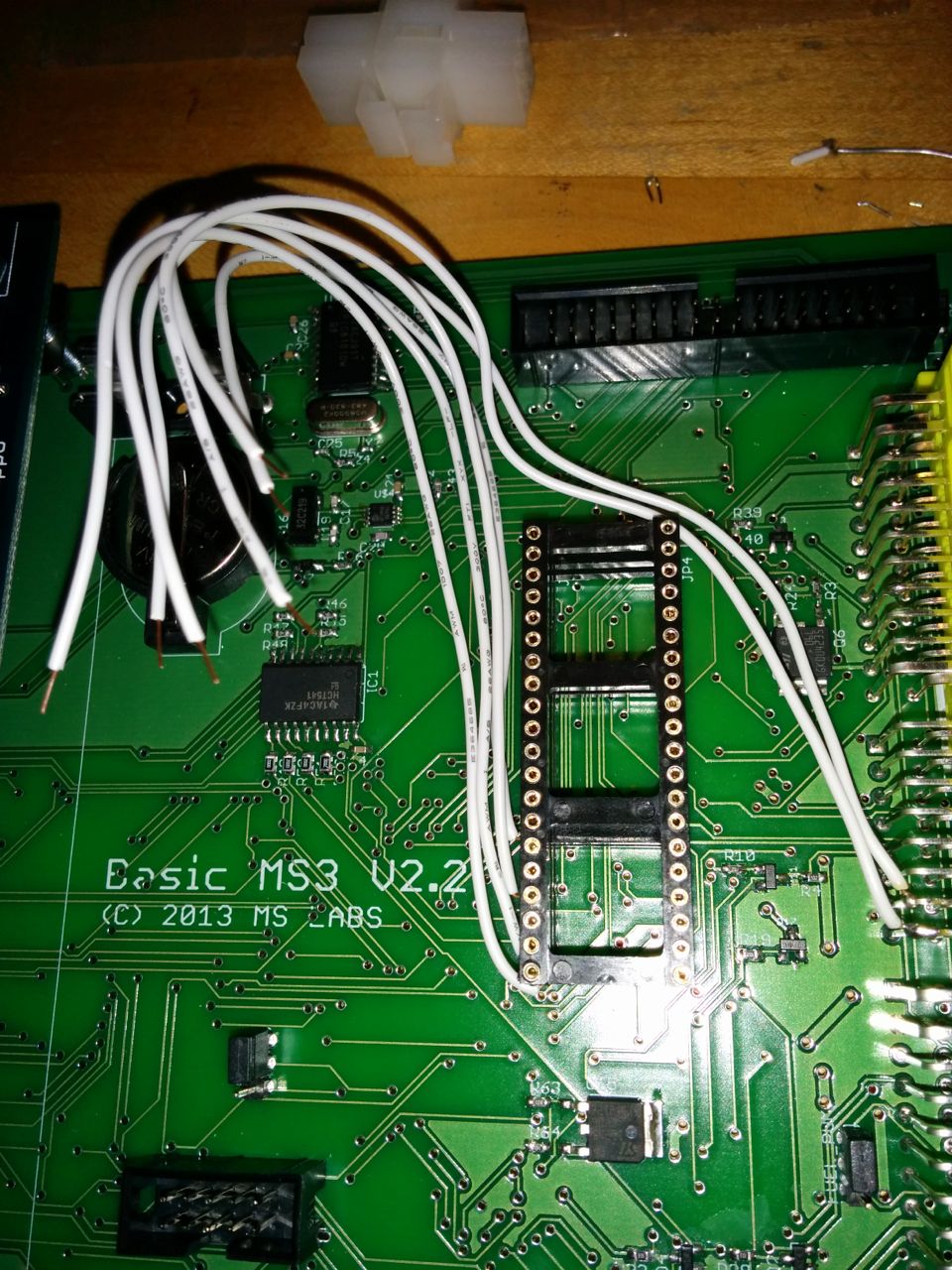
So yesterday we did some hacking on the MS3 to try to address the crank sensor noise issue. The inside of the case looks like this:
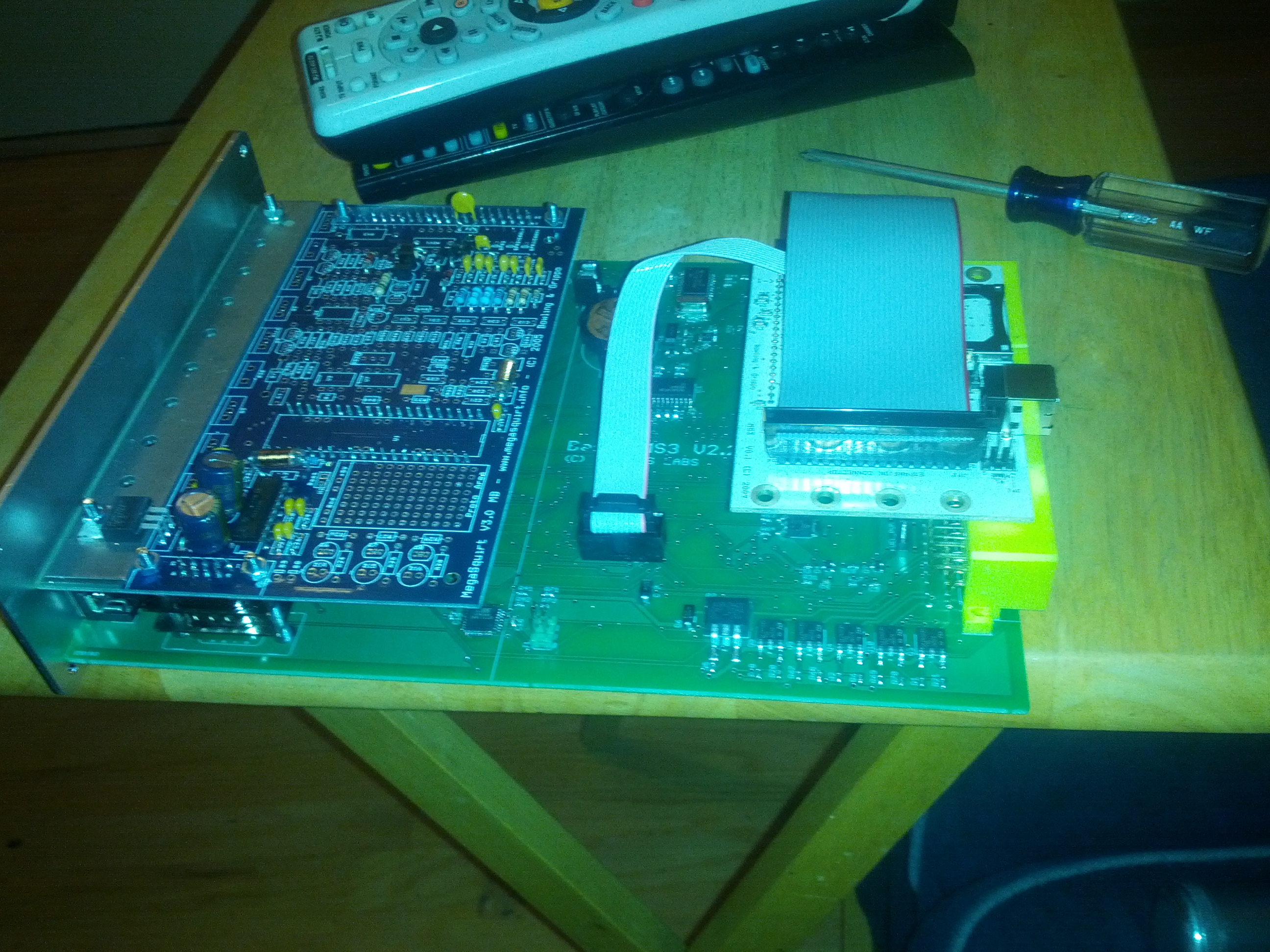
The cam and crank signals com in the Mazda connector (big yellow one on the right), cross the big green main board jumping through a bunch of vias on the way, go through an opto-isolator, up through a 40-pin DIP socket into the blue MS v3.0 board on the left, through an RC filter, back down the 40-pin DIP, back across the green board, up another stack of 40pin sockets into the white MS3 board on the right, and then into the surface-mount hc11 microcontroller's signal inputs. Looking at it on the scope, there's a lot of noise inside the MS3, more than there is on the factory signal wires.
I took ECE50A over 20 years ago and got a C- in it, so my direct knowledge of this kind of stuff is fuzzy. My (non-mt.netter) friend who's been helping out says this is not an ideal signal path, and that the opto-isolator may be causing the problems by not having enough hysteresis, so we decided to bypass it.
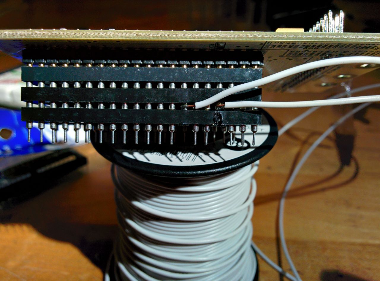
First some surgery on the 40-pin dip stack to disconnect the hc11 from the original filters:
Then de-pin the sensor inputs from the extension harness, build a filter circuit on a breadboard to test it, and hook it to the signals:
Then, when it worked, build a longer-term version on a proto board. The 2-pin sockets are for the filter resistors so that it's easy to change the frequency. I'll probably redo it once I'm happy with a particular value.
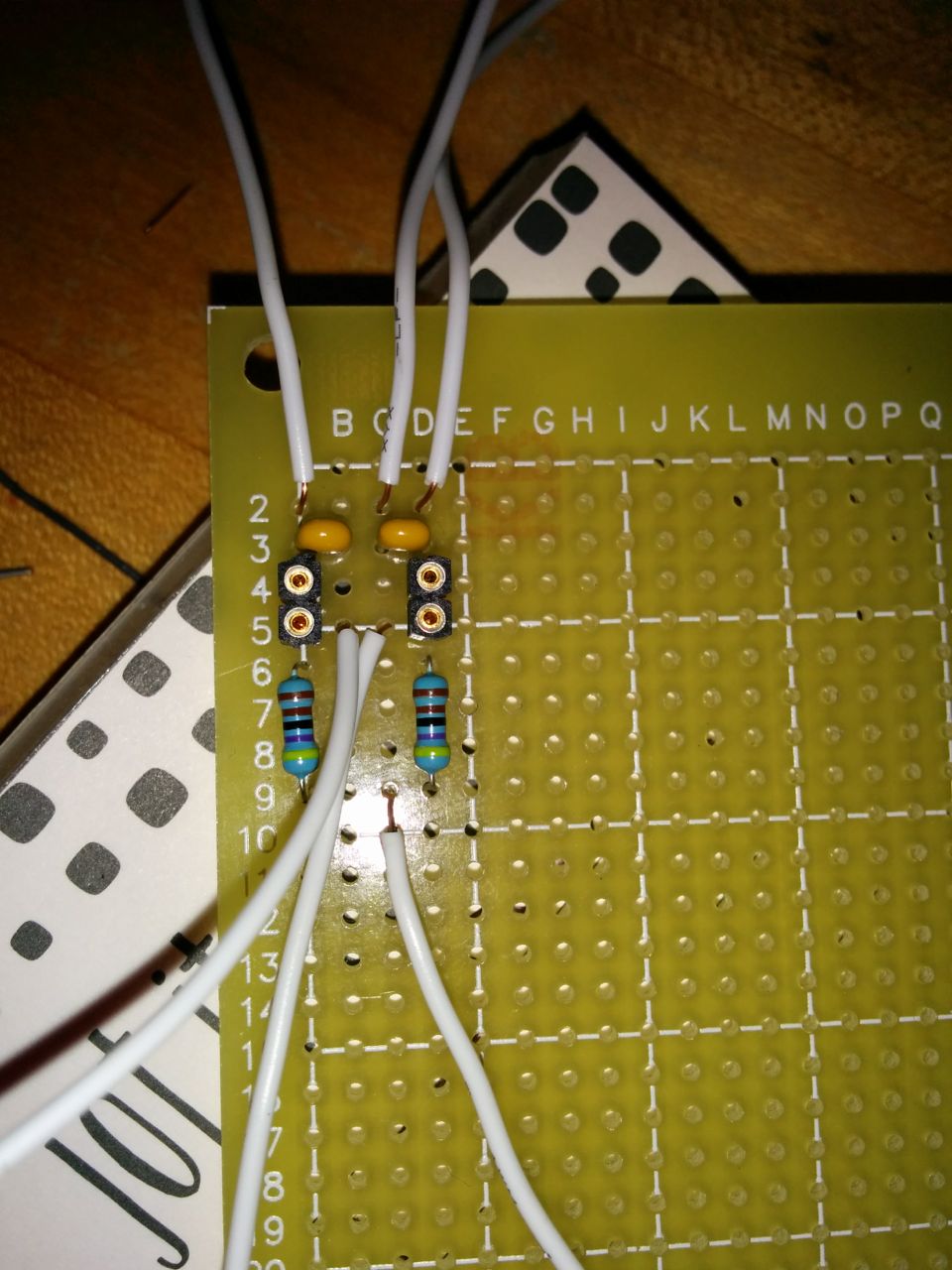
I soldered this myself! First thing I've soldered! And it works! Woohoo!
Then move the sensor inputs to two unused pins on the Mazda connector and hook wires to them:
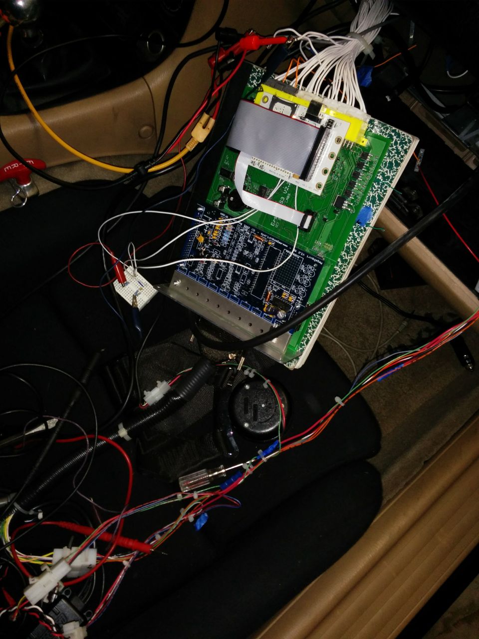
Then cut the proto board, connect it to the MS3, and mount it (forgot to get a picture of this).
The end result is that the car starts and idles, and will now actually run with the software filters inside the MS3 turned off. Previously, turning those off resulted a car that wouldn't even start without holding the throttle open and generated sync errors at a rate of 2-3 a second.
I haven't driven it enough to confirm that the every-20-to-30-minute sync error from before is gone (finished this about 1AM this morning), but initial indications are encouraging. Hopefully it's fixed!
Also, registered for Miatas @ MRLS this morning. Both days, group A again. Yay!
--Ian
The cam and crank signals com in the Mazda connector (big yellow one on the right), cross the big green main board jumping through a bunch of vias on the way, go through an opto-isolator, up through a 40-pin DIP socket into the blue MS v3.0 board on the left, through an RC filter, back down the 40-pin DIP, back across the green board, up another stack of 40pin sockets into the white MS3 board on the right, and then into the surface-mount hc11 microcontroller's signal inputs. Looking at it on the scope, there's a lot of noise inside the MS3, more than there is on the factory signal wires.
I took ECE50A over 20 years ago and got a C- in it, so my direct knowledge of this kind of stuff is fuzzy. My (non-mt.netter) friend who's been helping out says this is not an ideal signal path, and that the opto-isolator may be causing the problems by not having enough hysteresis, so we decided to bypass it.
First some surgery on the 40-pin dip stack to disconnect the hc11 from the original filters:
Then de-pin the sensor inputs from the extension harness, build a filter circuit on a breadboard to test it, and hook it to the signals:
Then, when it worked, build a longer-term version on a proto board. The 2-pin sockets are for the filter resistors so that it's easy to change the frequency. I'll probably redo it once I'm happy with a particular value.
I soldered this myself! First thing I've soldered! And it works! Woohoo!
Then move the sensor inputs to two unused pins on the Mazda connector and hook wires to them:
Then cut the proto board, connect it to the MS3, and mount it (forgot to get a picture of this).
The end result is that the car starts and idles, and will now actually run with the software filters inside the MS3 turned off. Previously, turning those off resulted a car that wouldn't even start without holding the throttle open and generated sync errors at a rate of 2-3 a second.
I haven't driven it enough to confirm that the every-20-to-30-minute sync error from before is gone (finished this about 1AM this morning), but initial indications are encouraging. Hopefully it's fixed!
Also, registered for Miatas @ MRLS this morning. Both days, group A again. Yay!
--Ian
Reply
1
1
 02-15-2015, 01:17 PM
#100
Elite Member
iTrader: (37)
Join Date: Apr 2010
Location: Very NorCal
Posts: 10,448
Total Cats: 1,900
Good show Ian, and thanks for documenting
Reply
0
0


