When you click on links to various merchants on this site and make a purchase, this can result in this site earning a commission. Affiliate programs and affiliations include, but are not limited to, the eBay Partner Network.
Warning! The following post contains horrible welding that may be disturbing to some audiences. Viewer discretion is advised.
First off, I want to thank a buddy of mine "L" who convinced me that I should just make my own exhaust vs buying one. "It will be so much cheaper & it's easy!" All I can say is that "L" obviously missed his calling. He easily had a lucrative career in selling yellow ice to eskimos.
Alright, with all of that out of the way...Let's discuss building the exhaust.
I decided I was going to do this over Christmas break last year. Family decided to bail on coming for the holiday (covid), so I had a good bit of time to kill. (Which is good, because I probably have 120+ hours in building this...)
My best decision with the exhaust was spending $100 bucks and buying this worn out band saw on Craigslist. It took me 3-4 hours to swap out the blade, grease it, and adjust it to cut square, but I'm very glad I purchased it. It's quiet, cuts straight every time, and doesn't make a huge mess or burn little holes in things. i.e. The complete opposite of a grinder with a cut off wheel...
She's ugly & adjusting her to cut square was a bitch, but super happy I bought this...
Planning:
My primitive man brain really wanted to run duel exhaust all the way back, because we all know the more exhaust pipes you have...the more hair you have on your chest, not to mention the +10hp per pipe you gain. Unfortunately, the no fun kill joy logical side of my brain took over and I decided to run a boring Y pipe back into a single exhaust so I could save on weight. I'm still a bit disappointed in myself making this logical adult decision, but nobody says I can't make a hairy chested exhaust later.
For pipe size, I decided to run 2.25" downpipes (the LFX has the exhaust manifolds built into the heads) to a "Y" and 3" out from there. I also decided to use aluminized steel, since I can't melt stainless with my MIG & I live in the south where the pipes should last a pretty long time. (I warned you this was about to get ugly...you can still bail now before the pictures!)
One common thread I have read from everyone who has built an LFX Miata is that the car is LOUD and most have swapped to a bigger muffler or added extra baffles/packing and used other witch craft to quiet the beast down some. I like a nice sounding exhaust, but I also like to be able to hear myself think and didn't really want to keep doing this over and over...so I decided to learn from others mistakes and go "big" on the quiet. To do this, I decided upon a resonator & a muffler. For the resonator, I went with a 18" vibrant resonator that's a straight through design. It probably will change the tone the most and quiet it down a very little, but since V6's aren't known for their pretty vocal cords...I figured this was a good choice to add a little quiet and make the sound more pleasant to the ear. For the muffler, I went with a large Magnaflow that everyone seems to run around here. I believe everyone refers to her as Maggie. Anyway, It's a straight through design too, so hopefully neither of them will choke the exhaust. I'm hoping this setup keeps the noise down to the low 90's and at least under 98dbs, since the track I run the most has that as the sound limit.
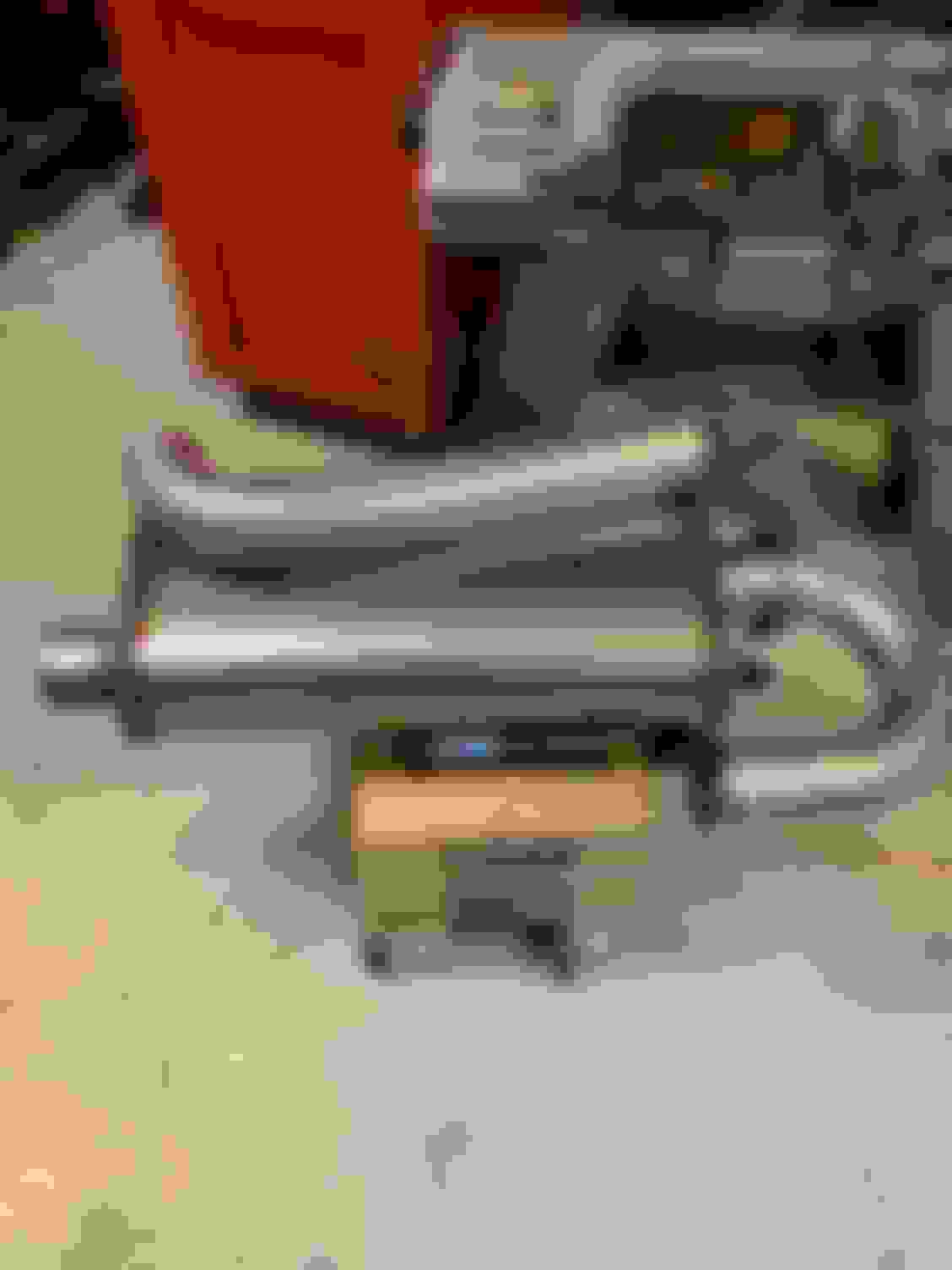
The resonator & Y pipe had to be shipped, but I laid everything out semi how it was supposed to all fit together.
Downpipes
I seriously thought about buying these already made. V8R has a 2.25" set, and Kiesler Automation has a 2.5" set, that fits an RX8 and are a beautiful piece of art, but would probably need to be chopped up to fit the Miata. Kiesler also sells 2.5" elbows (stubs) that you can build off from that are also beautiful pieces of art. Since my welding skill set is more stick men and hand turkeys, I decided upon modify the (supposedly) 2.25" stubs that came with the engine when I got it from the junkyard. (Can't mess up putting lipstick on a pig!)
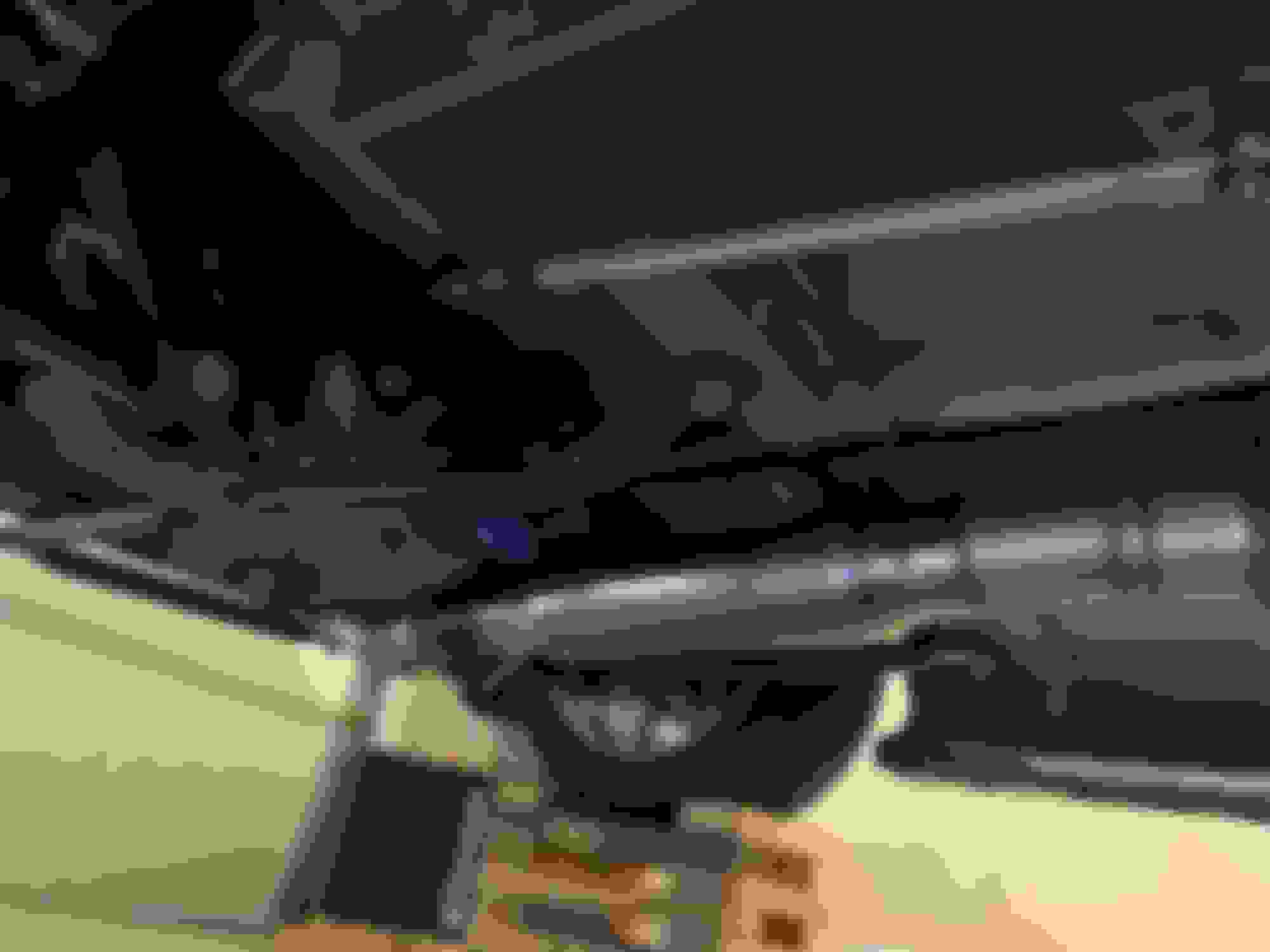
To get these things to even think about fitting, you have to cut the heat shields off them. I did this a while back "test" fitting in the engine bay previously, to see if modifying them was even an option. And although they are very close to touching, they do fit.
Only picture I could find with the heat shields still on them.
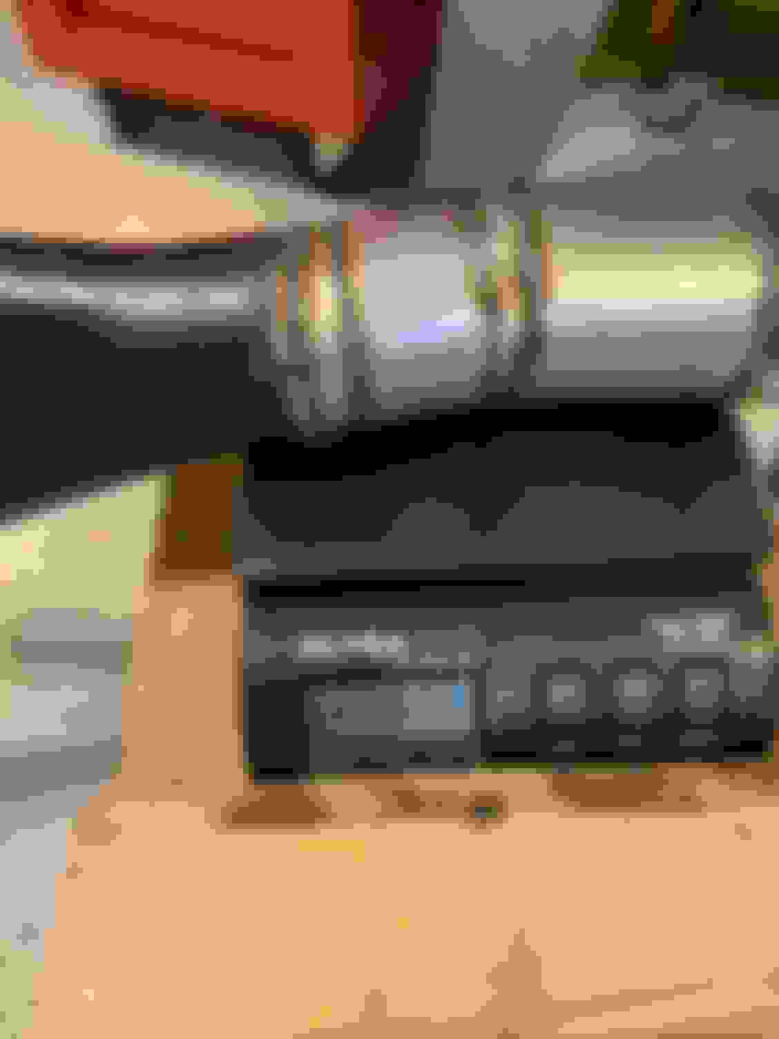
I would have loved to have kept them the length they were and modified from there, but they would have hit the subframe so I had to cut them shorter.
The one on the ground hasn't been cut shorter yet. This one was already cut once & looks like I'm about to cut it again.
The first cut wasn't short enough, the drivers side wasn't going to be short enough to get me past the steering column, so I cut them even shorter...I think I ended up cut them 3 times each.
I couldn't find a bi-metal bandsaw blade locally (and was to impatient to wait for amazon to try and deliver) so the new blade I just installed was missing teeth after about 10 cuts since the stubs are a stainless steel of some sort. At first I was a bit worried about going through blades, but nothing to worry about, a new "cheap" blade was under 10 bucks at Lowes and the second blade has lasted over 100+ cuts. on mild steel.
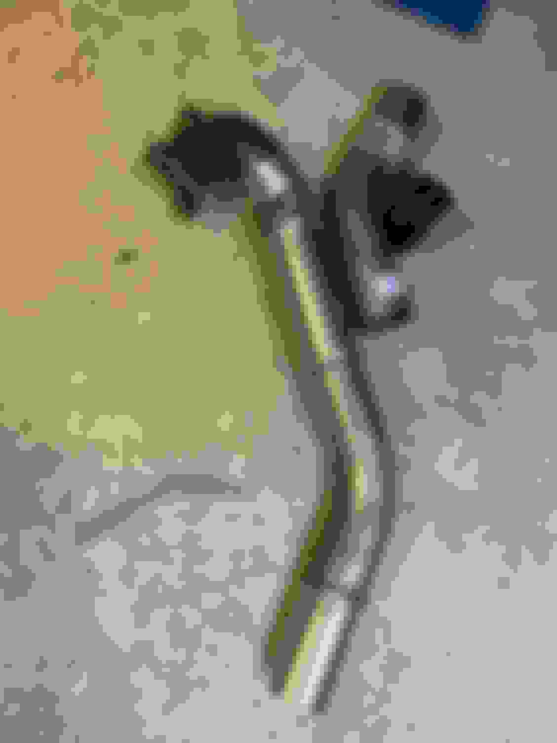
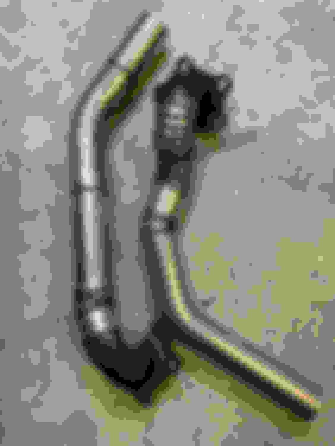
I wasn't sure if I was going to be able to make this work or not, so I started with the hardest part first, the drivers side with the steering shaft in the way. Unfortunately the Camaro cut "Stubs" point down first, when it would be better if they pointed more back and down at a 45 degree for the Miata. I couldn't figure out how to cut sections out of the mandrel bent 90 degree angles I purchased to get the odd angles I needed to get past the steering shaft. They needed to be tighter radiuses, so it was time for some pie. I cut a bunch of pie slices out of some straight tubing and quickly had a Dr. Octopus starter kit.
The first "pie" was actually still to large of a radius to clear the steering rack, so I made even tighter pieces.
Once I cleared the starter & steering shaft I was able to use a 45 degree piece to exit towards the back of the engine.
Crummy pic, but you get the idea
I used a jack stand and some blue painters tape to hold parts together to get the correct angle, since I wasn't tack welding this in the car (which would have been a lot faster if I felt comfortable doing that).
I also tied a string across the subframe that I used as the "bottom" and stopping points of the downpipes to keep them even at the exit. I'm not sure if this is the best place to stop them, but it seems to work well for my setup.
Picture angle is a bit funny here, the pipes are the hight of the string.
Once I had them all tack welded and made up it was time to start welding...and welding...and more welding. 1 inch at a time and then moving around or stopping and waiting trying to keep them from warping.
About to start welding here
Almost done with the "welding" here....
The passenger side came out much better & was easier to make since I didn't need as much pie (or welding) to get the job done.
One thing to note, was that I used 2.25" pipe because that was supposedly the pipe size Chevy used. I think the downpipes originally were more like 2" pipes and not very mandrel bent at the flange. I ended up hammering the 2.25" aluminized pipe onto the stubs vs butt welding them to the stubs as was the original plan.
Not very round!
I hammered this piece of 2.25 over the stub about 1/2 an inch
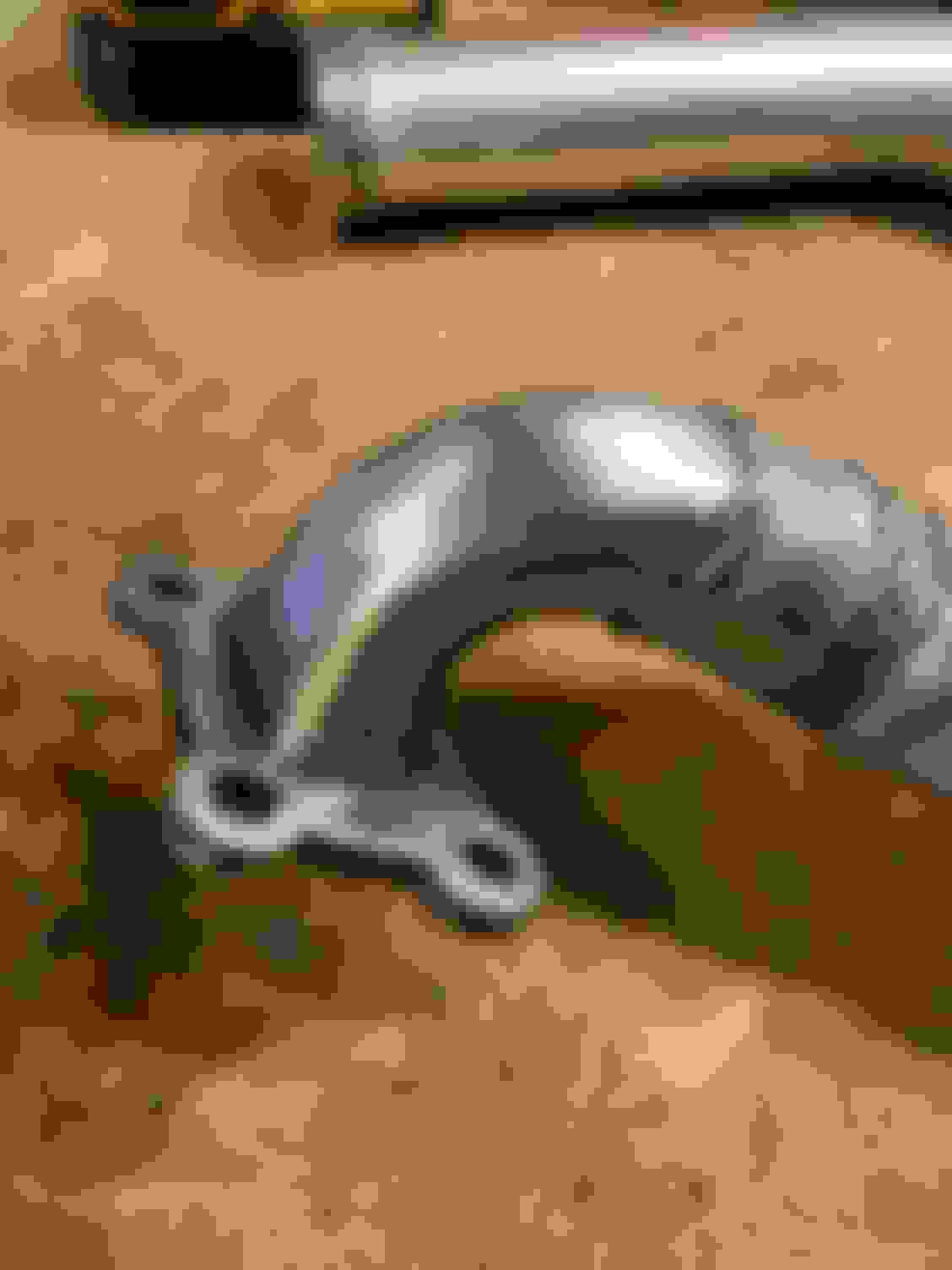
After a ton of welding, and only an inch at a time and moving to another spot or just stopping and waiting to keep the heat down...I ended up with these two "downpipes".
I welded on the flanges for the V-Bands and this is how they stayed while I worked on the rest of the exhaust. They were ugly, but I figured the hardest part was done. I thought under the car would be much easier since it basically sat in a single plane and the angles would be easier. This might be the case if you have a lift, but on your back under the car...no so much. These downpipes were actually easier to make.
The rest of the exhaust (which will be in the next post) was built off from the downpipes. After the rest of the exhaust was built I did modified / finished the pipes:
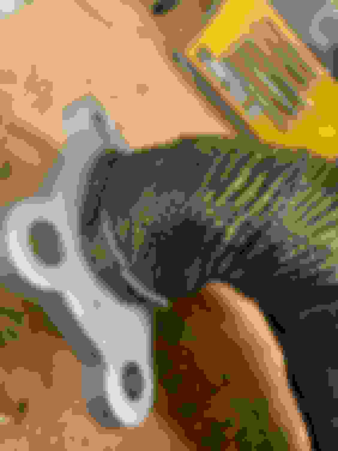
I drilled out a hole on each of them and welded in a bung for the front O2 sensors.
I also cleaned up all the rust & painted the headers with some DEI header paint. I'm doubtful this will do much, but with all the welding its gonna rust. If I can get 15K miles out of these pipes I'll be happy.
Once that all dried, I wrapped them to keep the heat down in the engine bay (and if I'm being honest, to hide some of that ugliness too!)
I just used safety wire to hold the wrap in place.
After they were all wrapped, I installed them with the metal gaskets and torqued the bolts down. Very last step was installing the O2 Sensors.
A for.... Affort? My eyes are burning but that might be from my own welds I know they are wrapped and installed but... maybe run them unwrapped to confirm you don't have any pin hole leaks? Spraying them down with some soapy water on start up would help you identify any leaks pretty quickly. Sorry in advance if my OCD causes you to do extra work!
A for.... Affort? My eyes are burning but that might be from my own welds I know they are wrapped and installed but... maybe run them unwrapped to confirm you don't have any pin hole leaks? Spraying them down with some soapy water on start up would help you identify any leaks pretty quickly. Sorry in advance if my OCD causes you to do extra work!
You Sir, have a Great Idea! I need to do that!
Annnnnnnnnnnnnnd...............
I'm gonna be that guy and totally ignore the great advice & just send it. I'm so OVER messing with the exhaust any more.
You totally reserve the right to say "I told you so" and it won't be held against you. (How often is that ever put in writing?) Hell, I'll even let MT.net know that it's making noises and it's a pin hole leak. (Right after you see a grown man throw a huge tantrum that would make a 2 year old proud...HA!)
Seriously, its great advice and if I wasn't so DONE with the exhaust at this point, I would do it.
Since I'm on the subject of grown men having tantrums...All of this finally arrived. I'm missing stuff still, but I have enough to start making a serious mess of things.
I'm gonna be that guy and totally ignore the great advice & just send it. I'm so OVER messing with the exhaust any more.
Ha, been there! Certainly not the end of the world. I would imagine the wrap should help dissipate any direct blowing heat but keep an eye on anything not metal *plastic, rubber, poly, etc.* for witness of melting/deformation. Someone I know recently melted the poly out of his engine mount and a sensor connector from a V band connection that was open. Obviously much worse than a pin hole leak but I am almost certified in worrying about minor details lol.
I definitely wouldn’t say I don’t have a pin hole leak somewhere...I know I’m not that good of a welder, but I feel confident that any hole I may have is small enough to not cause serious damage like your buddy had.
And Luke, I share the pain. I thought I was gonna shorten my time by building it quieter the first time around, learning from you and others, but I still have a bunch of time in it.
I’ve been busy with life/out of town the last couple weeks, so not much has been done on the Miata, hopefully I get some garage time this weekend.
The second part of our exhaust below...
Mid Pipe
This is a very long pipe & the pipe that gave me the most grief. (Might of been better to make this into two pipes if I do this again?) It also required me to be under the car on my back to build, so that wasn’t helping matters in the grief department.
I think this was the very first time welding it all up. I used the dollies to roll it out and back under the car easily.
I started by running pipes from the downpipes to around where I wanted the Y pipe. This wasn’t too bad, except I needed to put a little kink in the one to avoid a sensor on the transmission.
Here's the sensor I had to move the pipe around. Pipes running to the Y pipe.
The Y pipe was such a pain in the ***. I would say it was the hardest part of the entire exhaust. It’s an odd shape and didn't want to sit level on the jack stand, it was always wanting to fall off or twist in an odd way. Then I had the issue of getting the two pipes to line up going into it. It was a small nightmare. I also was connecting all of this at the transmission support brace, so less room for everything right here too. It may have been a smarter idea to run both pipes back a little further before putting in the Y pipe so the transmission support brace wasn't as much of a factor. Live and Learn.
Funny enough, I didn't take many pictures of the Y pipe part. (Probably because it was frustrating me so) You can see here that it's close to the transmission mount and keeping the pipes tucked under but not touching anything was a bit of a challenge
I used blue painters tape a lot to hold items together while test fitting. It worked surprisingly well. If you follow this path, make certain you keep the tape on the outside the entire time. I didn't and it was a bigger pain when it came to removing the tape & tack welding, since you semi lost your alignment by having to take the tape out of the crack.
You can see where I folded the tape over into the crack. This made it harder to remove / tack weld and keeping alignment
Once I got to the Y pipe, I had to wait a little bit for the resonator to arrive. I started putting all of that together, but realized that I had angled the pipes downward at the Y junction. I could probably have just left it like this, but with my luck I would have hit something and ripped the whole exhaust down. So, I re-did the pipes from the downpipes to the Y pipe to get everything tucked up there nicely. (If you are counting…This is the 2nd time I’ve redone this part, but it won’t be the last…ugggg)
You can see the Y pipe hanging lower than the frame rails. I seriously thought about just sending it, but I've bottomed out a car on the track (OK, I was 2 maybe 3ish wheels off) a couple times, I knew it would rip off eventually if I just left it. After the transmission mount, plenty of room to tuck the pipes up higher. I also was careful to keep the pipe as far off the passenger side (where I'm gonna need to hammer the trans tunnel in for my seat / install a drop seat eventually.
After redoing the pipes again, so everything was tucked up correctly, I worked more on getting the pipe around the diff to the muffler.
Here it is reworked so it's under the frame rails.
The Diff area is super tight, especially when you put the rear subframe brace on. You end up with about half an inch in every direction. Since I’m a one man band, under the car on my back…I used an old thick hand towel that was in the rag box. I wrapped it around the pipe and sort of jammed it into the spot I wanted. This kept it pretty much evenly spaced in the center where I needed it. I didn't take many pictures from the Y pipe back to the diff. Oddly this part was easier than the Y pipe. This picture is after I had most of this done & welded up and installing the hangers.
Once I got everything fitted up and tack welded I removed the whole pipe and welded her up. I thought I was being careful with the heat (and maybe I was, and i just moved the pipes a bit pulling it all down, since everything was only tack welded) but when I went to reinstall this pipe it didn’t line up with the downpipes. It had moved half an inch maybe a little more. UGG! I decided to give the whole thing a rest after that. I worked on other items for about a month before coming back to this problem child pipe. I don’t have any pictures of all of this, but I ended up redoing this a couple times until I decided to tack weld the parts of the pipe I needed while everything was attached under the car. Talk about no fun…I already barely can weld and now I was trying to do it under the car…
Sadly, things still remain a little off left to right, but I have the squareness spot on. (Not sure how I did that…) Anyway, if I slowly tighten the v bands a little on each side, I can get things to line up and looks like a decent seal. (We shall see once the car is up and running.) I'm guessing I'm bending everything a little bit so it all fits.
Both sides are off about equally as you see in this picture. I think some of my issue might have been the downpipes not entirely bolted down while I was building all of this.
Muffler
So I started messing with the fitment of the muffler while waiting for the resonator to arrive. Nothing crazy here, you do want to get the tightest radius U pipe for this. I believe I returned the first one I had (which was 5" and got the 4" radius that you see here.) The big 3" pipe and muffler require you to push all of it a bit further towards the back of the car to fit vs the OEM muffler position, it almost seems too big, but it will all fit. I cut & bent the heat guard a bit so things would fit better, where it curves down some, I bent it to be straight. For the “tailpipe” I didn’t do anything special, just lead it out the back like the OEM. I bought some black exhaust paint and may paint it black, I’m still undecided.
This picture is when I was tack welding the hangers in place, but gives a great idea of the U bend you need. You can also see how close the pipe is to the diff & such in this picture. The muffler isn't exactly middle of the car, it actually favors the passenger side (so I could get the U bend in) I was working on the tail pipe in this picture Everything tack welded up and ready to be welded up
A trick I learned after doing the downpipe V-bands, let the pipe extend out a little on one side so it self centers when you put it together. I wish I knew this trick when I did the front downpipes.
Hangers
I had purchased some hanger rods from Summit when I bought all the parts, but I think I only used one of them, and ended up just going to Home Depot Racing and buying a piece of steel rod and made my own. This ended up being a bit easier, since I wanted a little more length then the ones I bought had. I used the OEM hangers on the car to hold it all up and debated if I needed to install something more, but those 4 spots seem to be enough to hold everything properly. When I tack welded the hanger rods in place, I installed the rubber insulators first and the rods into them. Then I held the muffler / pipe up another 1/2” - 1” since I knew the rubber would stretch some. This worked about perfect. I purchased some poly insulators thinking they would hold everything up a little higher and not stretch as much, but from reading threads lately, it looks like the poly insulators like to melt and I’m better off with some new rubber ones and using a hose clamp if they start stretching too much. I’ll have to research this a bit more.
No pictures of all of this, but I pushed the exhaust around a good bit and nothing hit anything (honestly I'm a bit shocked about that.) Fingers crossed this is all I need to hold it up well.
Weight
This set up isn’t light by any means…46 lbs from the downpipes back, with about half of that weight being the muffler. I was really hoping for it to be lighter, but I’m sure it’s lighter than a dual exhaust setup, and it’s definitely a lot larger than stock / I did go big to keep it quiet. So, I guess 46lbs isn’t too bad with all that in mind. To lighten things up, I figured I could remove the muffler and just run pipe straight out the back, which would save me 20 lbs. or put a smaller muffler in place, saving maybe 10lbs then? But I really have to see how loud this car is before I start going crazy like that. I’m personally OK with 10/20 extra lbs if I don’t have to wear hearing aids the rest of my life!
Mid pipe weight
I cut a little off the tailpipe here, but I also added hangers to this & welded it up (and it's not in the weight) so I'm calling that a wash...
I really want to be ambitious and pull all of this down and clean up / paint the welds, but it might not happen. As I mentioned earlier, I'm really just done with the exhaust work!
Closest picture I could find of it all being done...obviously this is before the muffler was finished up though...
I feel your pain Brother. The exhaust was by far the hardest part of my build. I learned how to decently tig weld in the process though, and I had never tig welded before so that is a plus.
Stainless moving with heat was a constant issue for me. And the v-bands are just a nightmare with stainless. I ended up using marman flanges after two attempts of rewelding v-bands to get them to seal properly. Fingers crossed you are good, but if you run into issues like I did, check out the guys below for marman flanges.
These guys are awesome to deal with and do all kinds of crazy custom stuff.
On that 'U' bend, I wanted to open that out as far as practical, so I shopped for a muffler that had an inlet offset from the centre, and placed that to the rear. I figured it would help the gas flow better.
I feel your pain Brother. The exhaust was by far the hardest part of my build. I learned how to decently tig weld in the process though, and I had never tig welded before so that is a plus.
Stainless moving with heat was a constant issue for me. And the v-bands are just a nightmare with stainless. I ended up using marman flanges after two attempts of rewelding v-bands to get them to seal properly. Fingers crossed you are good, but if you run into issues like I did, check out the guys below for marman flanges.
These guys are awesome to deal with and do all kinds of crazy custom stuff.
SO HAPPY to be done with the exhaust. I really didn't expect it to be that much of a PITA. Fingers crossed those Vbands work. Those Maman flanges look cool, I seriously thought about them previously, but I couldn't find 2.25" flanges, and wanted everything "now" when I went to do this...so I just bought what Summit had on hand and drove down to get it. (They are 50 minutes from my house) At this point, there is a very large chance the car gets taken to a muffler shop to fix anything that pops up. I'm OK with being called a quiter!
Originally Posted by Gee Emm
On that 'U' bend, I wanted to open that out as far as practical, so I shopped for a muffler that had an inlet offset from the centre, and placed that to the rear. I figured it would help the gas flow better.
My original plan was your idea, and my muffler outlets were centered on one side and offset on the other so I could do that. I couldn't get it to work when I centered the Muffler behind the car (it's actually still off a little bit to get it to work on the other side with the tail pipe & the muffler outlet) the pipe going to the offset wouldn't fit without being too close to the shipping / tow hook and possibly hitting it with movement. (This is why I went back and got a U bend with a 1" tighter radius too.) Maybe I have my muffler to far forward, or should haven't have cared about trying to keep it centered?!? I was also trying to find space for the V Band connection and pipe coming out behind the diff & things not hitting each other. So I ended up flipping the muffler around (it's a flow through design) to get everything to fit. Honestly, I'm sure most of this is inexperience building an exhaust and trying to use 3" pipes & big muffler when the Miata is built for 1 7/8" pipes and smaller muffler. That's roughly 76mm vs 48mm for those who use the proper measuring system ;-)
Hard to take a picture under the car showing all of this. This picture looks like there is room, but it would be close.
Let the fun begin! I semi started this part of the project without a super clear idea of how everything was going to "connect" together. I had an idea about the LFX Engine Harness from when I made the prototype harness for the first engine start back in Feb. As far as the rest of the wiring, nothing concrete besides stripping unused wires out. I now have a pretty good idea of what I'm gonna do (with some questions below for all the people much wiser than me!)
I find it's simplest to break down the wiring into 3 main wiring harnesses / systems. Obviously they all connect together, but below is the logical break down...
Miata Chassis Harness - This is basically the Miata Fuse box on the drivers side under the dash & everything it "powers" I'm stripping this down to just the following items. Lights (headlights, turn, brakes, etc.), Wipers, & Power Windows (with the future goal of removing the power windows too)
LFX Engine Harness - This is basically the engine harness you can buy pre-modified harness from V8R or Kiesler Automation. The pre-made harnesses controls everything connected to the Engine, and a couple additional items, like the Gas Pedal, and OBD2. I'll modify mine a lot like the pre-modified ones, but I'll also be adding in the control of the cooling Fans & Fuel pump. (Those are left out of the pre-modified ones.)
Power Distribution Harness- On the stock Miata, this is the "cable" that runs under the car from the battery to the starter, alternator, and then the Fuse Box in the Engine Bay. I couldn't easily use any of this, it was either too short or too small of wire, so all of it will be new.
I'll go more in depth on all 3 harnesses as I modify / build them, but wanted to get eyes on my plans for the Power Distribution Harness, since I'm gonna be building it from scratch and want peoples thoughts on any changes that need to be made. Unfortunately you get this half backed pictures/diagrams, that's gonna make some electrical engineer out there cry, but it gets the ideas across.
Originally, I was gonna run the wiring like so...since it's all that I need to get the car running. NOTE: The power distribution block is a Bussmann 37702 single input with a relay that controls the "switched side" and two fuses for output, one for constant the other for switched. I didn't create the wheel here, I stole this from Gooflophaze who used it with one of his builds.
I want to install a Engine Kill Switch eventually, and figured this is something that I should do now vs hacking into the wires again later. For some reason, kill switch wiring is super confusing when you look at everyone's diagrams. Everyone seems to be wiring their kill switch up differently. All of this simplified a bit when I choose what switch (Longacre 45782) I wanted to run and looked at their instructions. Anyway, here is my confusing take on all of this too.
Sorry, I crossed lines on this diagram. I know that's bad form, but I was too laze to redo this.
Here is the Longacre wring directions...
Hopefully someone reading this can help me. I have the following questions...
1. Can I run 20awg wire off the power distribution block post to the relay? If not, where would you pick this power up at? Also, do I need a fuse for this / and the switch run of the relay? or is it low enough power to not worry about?
2. The Longacre Instructions show two leads from the battery going to the switch. I don't understand why you don't just run a jumper from A to B, instead of separate runs? I'm also guessing this would be 6 awg wire just like the alternator wire? Anyone see any issues running a jumper?
3. Running the cut off switch this way will kill the "Battery Backup Memory" on the ECU, so it will have to re-learn stuff every time this is thrown. Would you keep it this way? (Safest?) or would you just run a wire from the battery all the way to the computer so it always has the battery back up connected?
4. See anything else that should be fixed / changed?
Although that welding did hurt my soul a bit I'm glad to see the project moving forward lol.
If you can spare the extra cash I would really look into a Cartek or MSEL solid state battery isolator so you don't have to run monster wires to a switch. Some of them you can do cool stuff like read data and errors via CAN if you have the means to do so, and have an ECU or PDM trigger it, for example if the car is upside down you can have it auto shut off, or if you hit 6 g's on your accelerometer from an impact etc.
I have the MSEL when it went on black friday sale from RaceSpec when I ordered a ton of wiring components.
LOL...The welding hurt my eyes a bit too, but the exhaust is an easy bolt on, so not a huge deal to replace at a later time. I need to practice my welding. I have a hard time keeping a consistent distance with my stick out while welding the pipes. (I'm sure I have other issues too, but that's the one I really noticed.)
I had previously looked at the solid state battery isolators (specifically the Cartek) a while back. I'm a fan, and thank you for bringing it up, but they are hundreds more than a basic switch. I need to keep financials in check (HA!) and I can spend that money on other safety equipment that I feel would offer more bang for the buck right now...(i.e. cage vs roll bar, fire bottle vs hand held, halo seat vs my aluminum kirkey)
1. Can I run 20awg wire off the power distribution block post to the relay? If not, where would you pick this power up at? Also, do I need a fuse for this / and the switch run of the relay? or is it low enough power to not worry about?
2. The Longacre Instructions show two leads from the battery going to the switch. I don't understand why you don't just run a jumper from A to B, instead of separate runs? I'm also guessing this would be 6 awg wire just like the alternator wire? Anyone see any issues running a jumper?
3. Running the cut off switch this way will kill the "Battery Backup Memory" on the ECU, so it will have to re-learn stuff every time this is thrown. Would you keep it this way? (Safest?) or would you just run a wire from the battery all the way to the computer so it always has the battery back up connected?
4. See anything else that should be fixed / changed?
1. In ours, key-run provides the hot side to the PDU, but that's in keeping with stock miata wiring. Wire thickness is determined by draw, relay is going to be well below 1a, 20awg should be fine - I run 18 because I have a lot of 18awg.
2a. can't comment, maybe something race-body specific 2b. wire gauge is determined by amps and length. Higher the amps and longer the run, higher the internal resistance, hotter it gets - there are some charts online to act as a guide, some of them are a bit conservative in my opinion. I felt comfortable with my 2 feet of 8awg from the alt to the fusebox, but if the battery disconnect is trunk mounted I'd definitely think about bumping it up to 2-4.
3. Battery backup is just going to be holding short and long term fuel trims along with ECU codes. Ultimately I think it depends on your 'tune'. Wonder if running something like a supercap would be permissable (I haven't measured it, but I doubt the battery backup is drawing more than 50ma....)
4. I've re-re-re-redone the LFX's fusebox again, and added about 2 feet to the power wires from the LFX's harness to position the fusebox better in the engine bay. We've also had a case of 'dieseling' after turning the key off twice now, but I haven't been able to track down the culprit - something backfeeding the system, keeping the PDM relay charged - disconnecting the relay completely has successfully killed the engine. Might just be our ignition switch is tired and arcing. It happens rarely, but when it does I need to start pulling fuses next time to figure out which circuit is doing it.
Gooflophaze...Thank you! A few additional comments...
1. Great...I thought it was OK, but it seemed odd putting such a small wire with that large of one.
2. Kill Switch will be in the center of the dash (where the radio use to live)...I'm just going to use the alt wire that Chevy had on the engine to begin with and I believe it's 6 awg. I'm thinking the run will be the same or maybe shorter than the original run from the starter to the Alt.
3. The battery backup is a 0.8mm (18awg) from the factory. I thought it pulled a bit more than 50ma from the wire size...either way, I know nothing powers up if you don't have power on that line. LOL Took me a couple hours with my beta throw away harness to realize that, because I didn't run any power to it originally. The Supercap idea is very interesting. (I very briefly read about them, and didn't realize you could use one as a temp "battery") My only experience with capacitors is with compressors (AC/Fridge). Guessing I would just wire is up after the fuse inline? How do I figure out what "size" capacitor I would need? (If you just know this stuff off the top of your head, I can also go read up on it.)
4. I plan on using some GT280 connectors in place of the body harness connector & the fuse box connector. (not sure if those are the proper names, but I think you know what I'm talking about) I thought about running the fuse box (and power distribution) inside on the passenger firewall vs keeping in the engine bay. I was thinking this would give me a little more room & keep the electrical a little more "out of the elements" if you will. Which sounds very similar to what you just did.
The LFX is Dieseling?!?! I haven't seen a car do that in a very long time. I immediately think, hot day/engine with a carb that needs to be rebuilt. Anyway, I'm no longer using my ignition switch with this build. Its from an NB, but it's yours if you want it.
Lastly, I've read your wiring write up at least 10 times now and I get something new out of it every time. THANK YOU!!! It's been a huge help!
Supercap feasibility is gonna be dependent on what the ECU off-draw is - it was something I briefly considered while trying to figure out our no-start that turned out to be clogged fuel filter, so can't say I fully explored the idea. If the off-draw is more than 1mA, I wouldn't consider it feasible - I have to imagine the circuit is also integrated for more of the GM hardware, like if you unlock your camaro doors it'll send a wakeup signal to the ECU that might start doing... "something" and pulling current through that connection. I think the 1ma threshold is indicative of "yeah, this just backs up the sram" operation. Sizing is gonna require math - and also finding a supercap that'll support 25-30v (normally you want to at least double your voltage rating on capacitors) without being overly-exotic. Most supercap applications are replacing coin-cell lithium batteries - don't want to size one that could also power a rail gun if negligently discharged in the engine bay....
Dieseling is the wrong technical term, but yeah, "keeps running with key turned off" pretty well describes it. I just had a memory pop up though.. I ran one of the fan power sources from the stock miata fusebox, I wonder if that's backfeeding the Eaton fuse box... might also explain why it only happens sometimes and not often enough to troubleshoot easily.. I see toting my fluke into the garage in the future... But either way if you pop the hood and disconnect the 2-pin relay connector, engine shuts down.
A quick update on items that I finished a little while back & this finally gets me pretty much up to date on the build thread! I've been playing around with the wiring, but not enough to write up yet.
Body
I have what looks like a car again! (Well, minus the rear wheels off due to the axle nut issue that I'm still working with V8R on, but I’m not gonna be greedy here!)
Not much to say about reinstalling the front fenders & the front bumper etc. I pretty much just installed all of that back as stock. Future plans will be to cut out the bumper support and install a radiator support bar / quick disconnects, but this works for now.
I'm probably gonna need an interim ducting solution for the radiator…there is a lot of open space around it with the stock setup. For now, I’m gonna wait and see about all of that, since I rather do it while removing the front bumper support etc.
Hood
The hood needed to be modified to close since the LFX engine is so tall. Lucky for me, I have an NB, and only need to cut out the ribs. This was super simple, I just put some tape as a guide line and pulled out the grinder. Slow and steady and you can cut out the ribs without messing up anything else.
This was the first cut, I installed the hood & it would close, but the bottom ribs (which are at the top of this picture) were really too close (didn't pass the grease test) so I cut them out too.
As far as the glue that is also used to hold everything in place…it’s not very strong at all. It’s super easy to just pop off by hand. I was expecting 3m double sided tape type strong, when it was more like a post it note strong.
Another mod to the hood was to the hood latch mechanism. The plan is to run some aero latches (or something similar) to hold the hood in place verses the latch, but reinstalling the latch is 3 screws worth of work…so I hit the easy button for now. I had previously removed the hood release cable, and I didn’t want to reinstall that, so I just used a little line that I had laying around, stopper knot in one end, bowline in the other, and voila…hood release cable that weights almost nothing and took all of 3 minutes to “install”
Oh, I almost forgot the best part...The chromed out windshield washer lights. I think I mentioned before that I've been slowly removing the Pepboys pimp my ride stuff from the car...this was the hoods contribution. These are tacky enough they almost just got left on the car for laughs. Like most of the gaudy crap, they weren't wired up correctly...but I wanted to see one in action, so I wired one up to a battery really quick on my bench.
Lastly the hood prop. I didn’t have a way of clamping it in place when not used after modifying the radiator supports, and I wasn’t too crazy about it either. I know I could do the piece of wood in the trunk version too, but that just seemed like a PITA to carry around all the time (cause you know it won't be left in the trunk when you actually need it.) So, I checked out hood supports and really liked the Flyin Miata setup. It’s clean and out of the way when you need to work on the car. They were on backorder for a couple months, so I decided to just source my own parts and build it myself. I like the current setup, but I may buy a little stronger set of struts. These work at holding the hood up, but a strong breeze directly on the back of the hood would probably be all that’s needed for it to come crashing down. These were 24lbs (a piece) struts, I’m thinking 30lbs struts would be “just right”.
Installed upside down, but they fit better that way.
Hardest part of the hood props was these damn ball studs. I ended up with 3 different sets & none of them worked properly. This set is the one I ended up using, but I had to go get a die and remove the shoulder on 3 of the bolts. (The 4th ball stud in this picture was the only correct one I received.)
That little shoulder was the difference between the struts fitting in the spot or not.
Picture of the hood all finished up...
Fender Roll
I rolled the rear fenders. This was a bit more time / harder than it looks. I purchased a used (cheap) fender roller off craigslist and it just barely fit (too big, I had to remove the coilovers to get enough hight to roll them). Rolling the top of the fender wasn’t that hard, but starting down the top/side some was a lot harder, especially where the pinch welds are. Anyway, using a heat gun & the roller I got them rolled. I’m not sure if what I have is considered a “flat” roll or not (I consider flat being the two pieces squished together touching, where I have more of a U shape with both pieces of metal parallel with each other.) I think if I roll it any further I’m probably gonna crack the paint.
Setting everything up to start the rolling...
This is the area where it gets hard...especially at those pinch welds.
As far as the front fenders, there really was nothing to roll up there (maybe I’m wrong about this?) but I ended up bending the tabs that hold the fender liner up and out of the way. (Sorry no pic)
This gave me all the room & then some with my 225’s on 9” rims (with a 5mm spacer). I think I should still be good with 245’s on a 9”, but I’m not sure about the 245’s on a 10”. For now, it’s a wait and see, I can always roll/pull them more if needs be.
Sorry, I didn't take a photo of the wheel after rolling, and they are off right now while I wait for some parts from V8R, but here is a shot before I rolled them and you can see how close the wheel was / is to the fender & why I decided to do roll them now.
It's been a little bit since I last updated. I've gotten a few things done, but not as much as I was hoping. Been busy with some other jobs lately.
Axle Nuts:
I spent half a day removing the half shafts & hubs and boxing them up to ship out to the drive shaft shop, who is V8R's vendor that originally made them. They are working on fixing them so I have enough threads for the axle nuts to lock down properly. Fingers crossed I get them back in a week or so.
2 Steps forward...1 Step back!
Switch Panel:
I bought this huge sheet of plastic (it's gonna be for the air damn eventually) and cut out a little piece to use for the switch panel.
Once I cut out a workable size piece, I slowly cut it to size with a razor blade and used a heat gun to get the curve into it, just using the plastic NB "tombstone" frame as a guide. Once I had it close, I pulled out a palm sander to clean up the edges & voila...
Bent into shape with the heat gun & used some clamps to hold it to the NB tombstone trim.
This all gets held in place by nothing fancy, just two screws on each side.
I took a moment and figured out where I wanted everything on a sheet of paper first. The idea here was to keep the same items grouped together and try to keep the switches out of the way of my hand on the gear shift as much as possible too. I also laid out space for items that I'll be adding later to the car. (fire bottle & brake bias adjuster)
I then took out a piece of grid paper and taped it to the panel and laid out where I wanted to drill the holes. This made everything nice & straight / evenly spaced.
Still needed to drill the hole for the Kill Switch in this picture...I was waiting on it to arrive.
Once I had my holes drilled I inserted all my switches in place & test fit it again. I was a bit too close to the edge on a couple of the switches, but with a little persuasion I managed to get everything in there. Its a bit shiny and I'm not crazy about that, so I may paint it or wrap it in some vinyl. That can be done once the car is up and running.
Miata Wire Harness: I've also been working on stripping out all of the unnecessary Miata wires from the wiring harness...and let me just say, there is a ton of them to remove. I have pretty much everything I no longer need removed now.
Original Harnesses (Most of it...minus the doors & rear harness)
Stripped Harness (I actually removed a good bit more wires from the harness still, but I didn't take a picture afterwards.)
Filled up a 5 gallon bucket with wires I no longer need! (& shockingly there are wires not in this bucket...This is about 12lbs of wiring)
I pulled the dash so I could easily "reinstall" the harness in car / work on it. I routed the wires & test my circuits to make certain they all still work properly. (Spoiler Alert...Everything works & No Smoke!) I also decided to move the relays that are originally in the engine bay inside the car. This just made more sense with everything else being moved into the car. (I still need to shorten those wires) and to install all of this on a "Wire Wall" on the passenger side firewall. (That I still need to build.) I'm also gonna move the Miata fuse box over to that area too. That requires just elongating one wire to do. This will keep all the electrical in one nice (and hopefully) neat spot.
I'll write up exactly what I did more in depth later.
I've also been shopping / buying a bunch of little odds and ends needed for wiring. That has been a major time suck. I've also been doing research on LifePo4 batteries. I'm debating if I try running one right off the bat or if I go with a traditional battery for now.
That's about it for now. I'm hoping next week things start to slow down and I can work on her a bit more again. Fingers crossed!
I'm doing a similar loom simplification for my na/mk1 Eunos car, it's amazing the 'extra' wire Mazda used to run relays & splices then cross back over the car

 06-03-2021, 10:25 PM


 2
2


 I know they are wrapped and installed but... maybe run them unwrapped to confirm you don't have any pin hole leaks? Spraying them down with some soapy water on start up would help you identify any leaks pretty quickly. Sorry in advance if my OCD causes you to do extra work!