When you click on links to various merchants on this site and make a purchase, this can result in this site earning a commission. Affiliate programs and affiliations include, but are not limited to, the eBay Partner Network.
You're really going to love those handles/gussets. Keep in mind I'm not an expert welder, but next time you're working on a cage, try pre-heating the metal with a propane torch, or turning up the machine, or both. Your welds if anything, look cold. You'll be hard pressed to burn through .095 or .120 wall tubing, so there's no reason not to turn the heat to damn near max.
Thanks for the advice! Sadly, I tried both turning up the machine and heating the bars first (I didn't try doing both at the same time). Neither seemed to work any better for me. On the tube I heated (used MAP gas, it wasn't glowing or anything, but it was definitely hot even with a glove on) I had the same welding results as not heating it up. I also tried turning up the machine. and that caused a bunch of splatter, which I almost never have since I started using gas, but the welds didn't look hotter / penetrate better, just making more of a mess.
I did test / practice a little before hand. If I can get the nozzle in very close (and the stick out short) I got decent heat / penetration...which you can see on the flat areas on both sides of the tube I tested with, but once the tubes start to get in my way and I can't get the nozzle in as close, I had colder welds.
Obviously, I need more practice. Especially when the tubes aren't "butt welded" on the same plane vs more of a corner type joint. I've been thinking about signing up for a weekend welding class, probably would do me well to have someone professional show me what to do / what I'm doing wrong. But like everything else, its finding the time.
Can’t believe it’s spring already and time to start tracking the car again. In racer fashion, the car was all torn apart from the winter’s break and I’ve been rushing for the last month to get **** done so I can drive it. Happily I can report, I got her back together enough for my first event last weekend!
The idea for all this down time over the winter was the following: (in no specific order)
Finish up the “Safety” (Cage, Seats, Harnesses, etc.)
Work on Cooling (brakes, radiator ducting, hood vents, etc.)
Install gauges & lap timer (AIM PDM32 kit)
Little odds and ends
Aero
Writing down my list all at once makes it feel a lot bigger then what I was thinking in my mind. I JUST received the AIM PDM32 I purchased back in May last year (10 months!!!…I picked it up on Sunday last weekend while at the track.) So that got taken off the list by default. I’m also still waiting on the hood & fender vents (Fedex says Monday) and the brakes / radiator ducting had to wait until after the air dam with the aero was installed…so that was placed lower on the list / wasn’t worked on yet either.
Which left me working on the “Finishing up Safety”, “Little Odds & Ends”, and “Aero”.
Let’s start with “Little Odds & Ends” and go from there…(Note, I didn’t do this in the order that its written.)
Finished the Drop Floor
I used a bunch of seam sealer on the drop floor and painted it. (I hate working under cars...painting under a car on jack stands really sucks!)
I know seam sealer isn't normally put on race cars...but I'll take the extra weight of seam sealer to keep it from rusting.
Oddly enough this is the best picture of it painted. (and before all of the new heat insulation is installed.) You can see how thin and runny the VVT epoxy paint is.
Added More Insulation in the Tunnel
I always burn my hand touching the tunnel, especially getting out of the car. I took a two fold approach to this problem. (First I bought racing gloves, which I should have already had…) and second, I added some more insulation under the car. (this is a 2’ x 2’ piece, the first piece I already installed was 4’ x 2’ incase you are trying to cover the entire tunnel…)
Same idea as before…I made some templates out of some thick floor protection paper and cut it out with some tin snips
Stuck it to the car and then covered all the seams so water doesn’t get into the insulation. (I may need to go back and do some more of this…some of the tape was lifting.)
Battery Hold Down
I finished this up…painted it with a can of paint that was on it's way out, of course it spit the paint out...oh well. Afterwards, I used some double sided tape to attach some padding to each clamp. Doesn’t look the best, but it works and isn’t rusty.
Gas Pull & Trunk Pull
I no longer need a key to start the car & I don’t have a fuel gauge right now. So I find myself going to the gas station A LOT to top off and then going “Ahh…****, I forgot the key to the trunk” So this change is a welcome addition to the car.
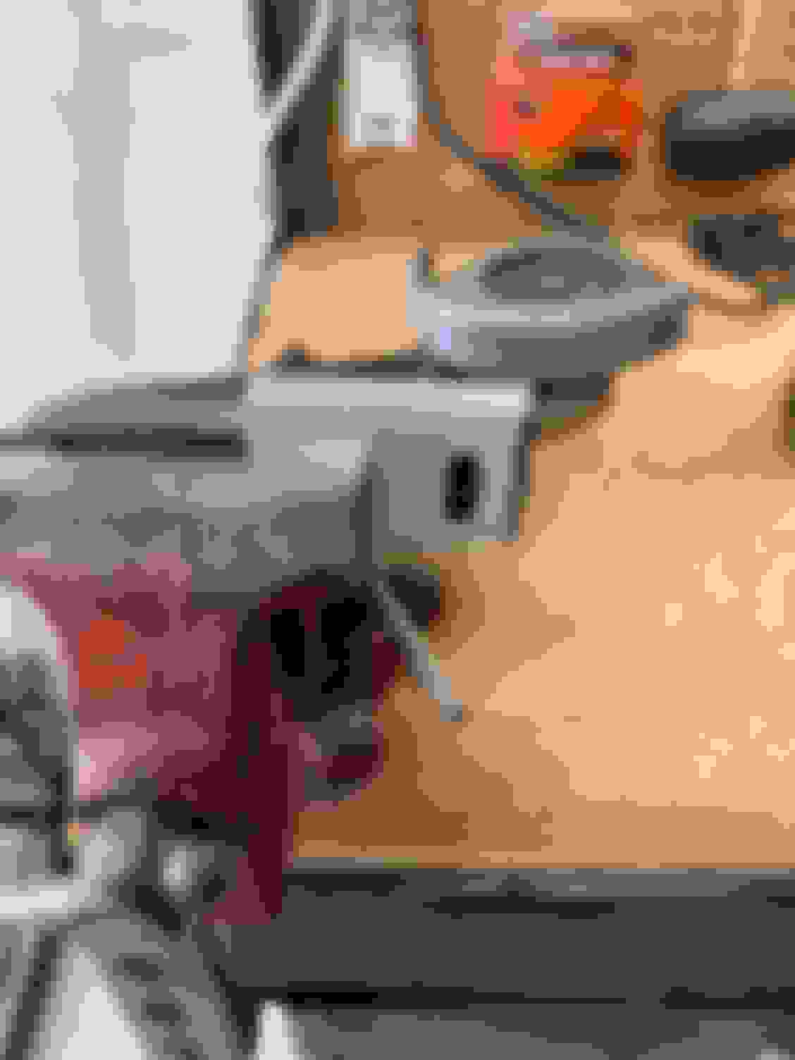
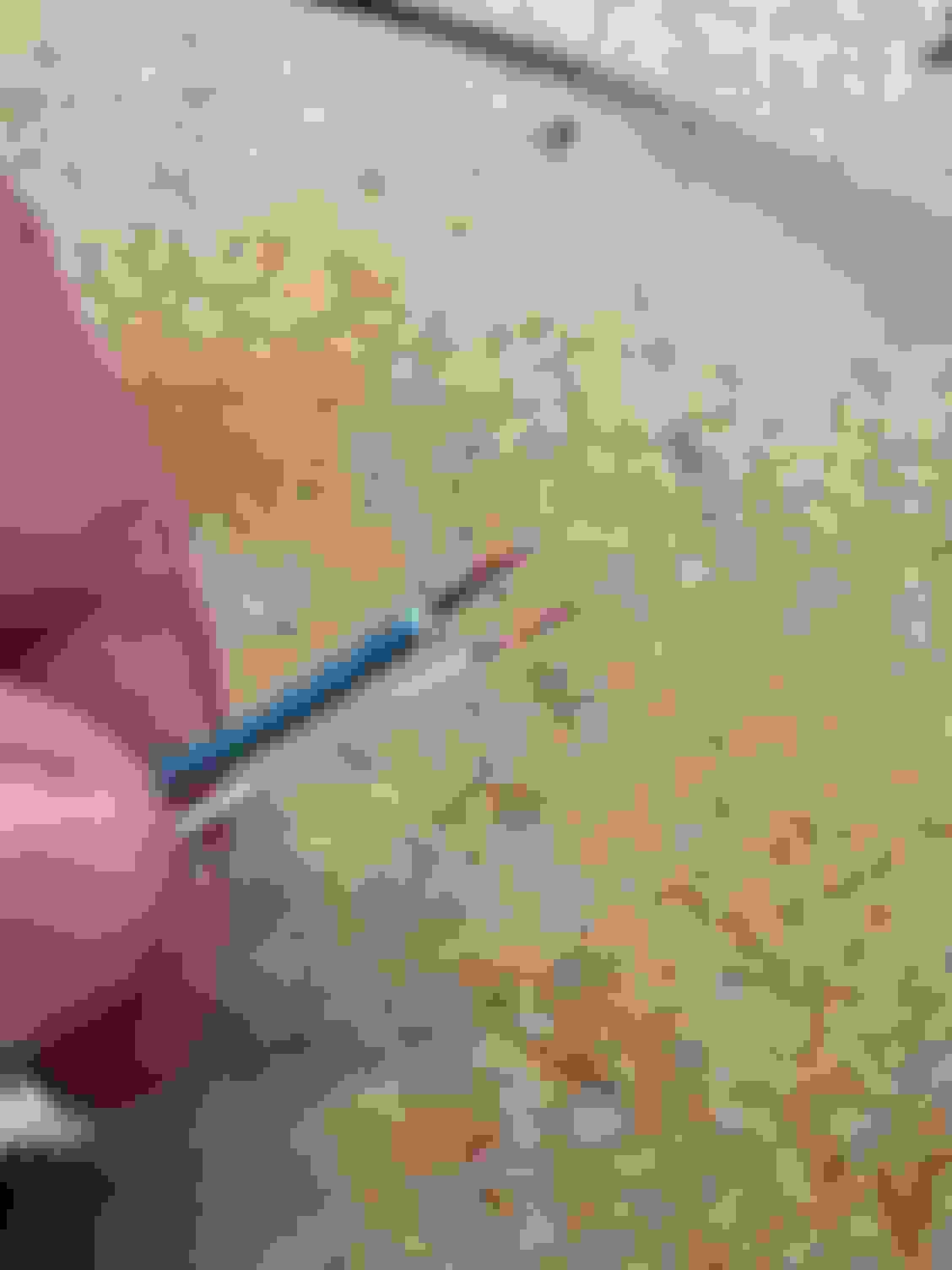
I started with adding a Gas Pull when I put the fuel pieces back that I removed to paint the cage.
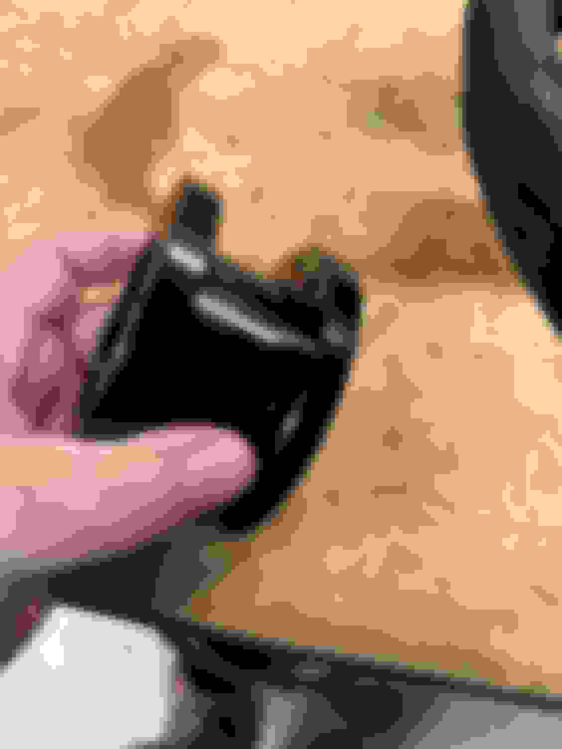
Where is the latch for the gas cover. Previously I was reaching up in the trunk and pulling a little bar on this latch to get it to open.
Using the original cable, I cut a piece off to modify Pulled the sheath off and made cut it so I had a much smaller piece with the plastic end that holds it to the latch
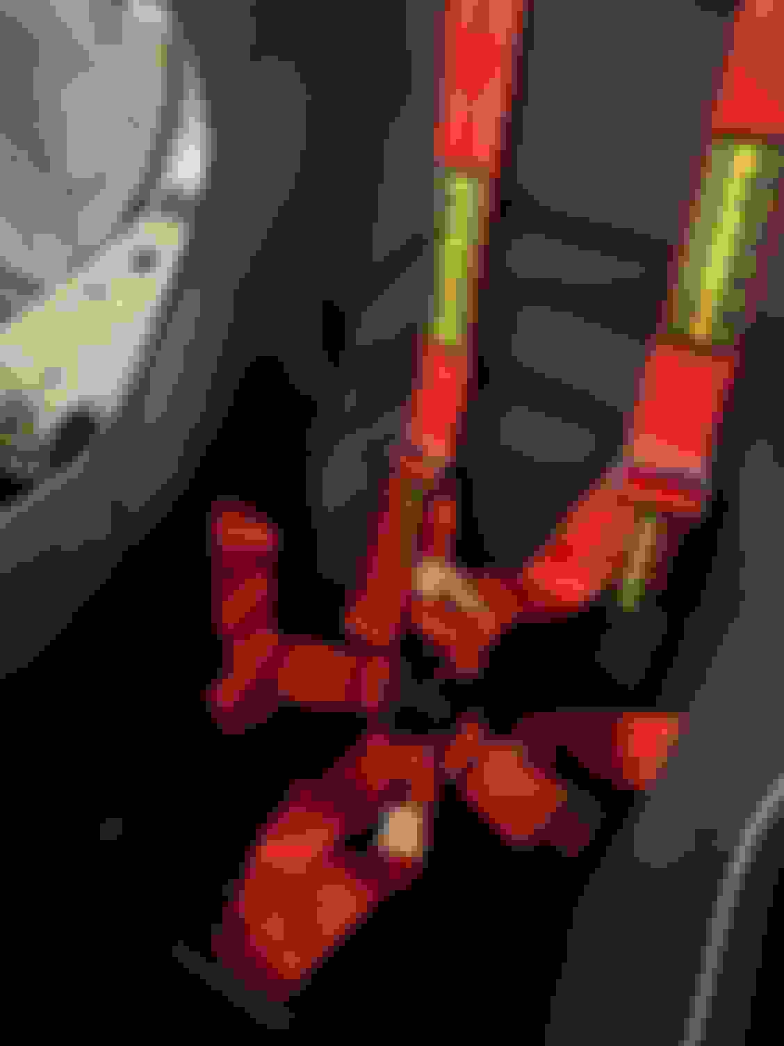
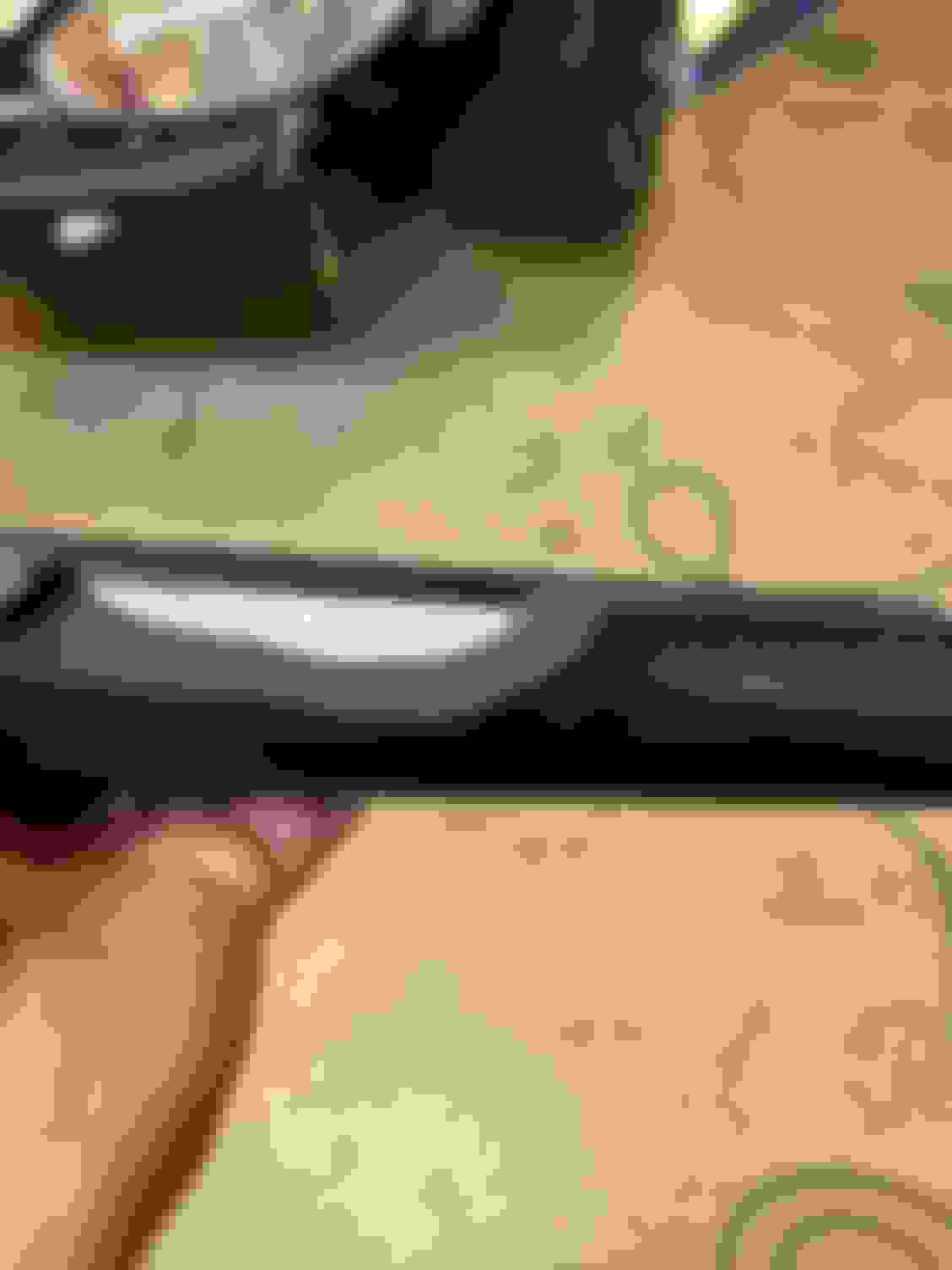
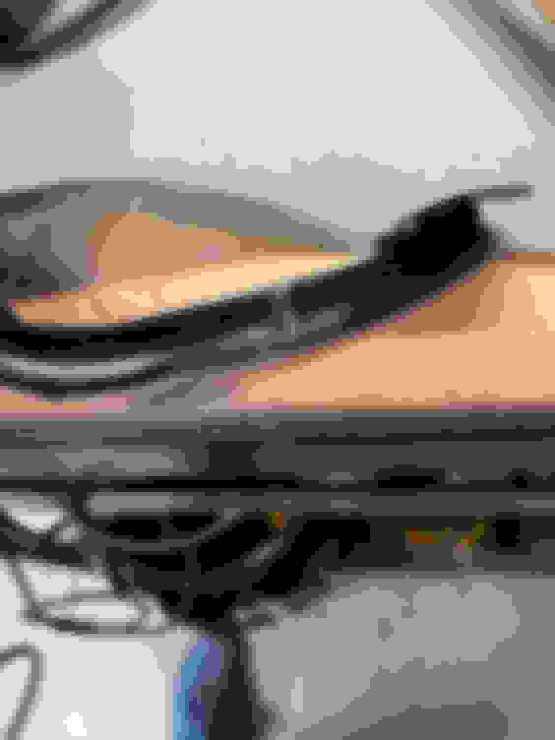
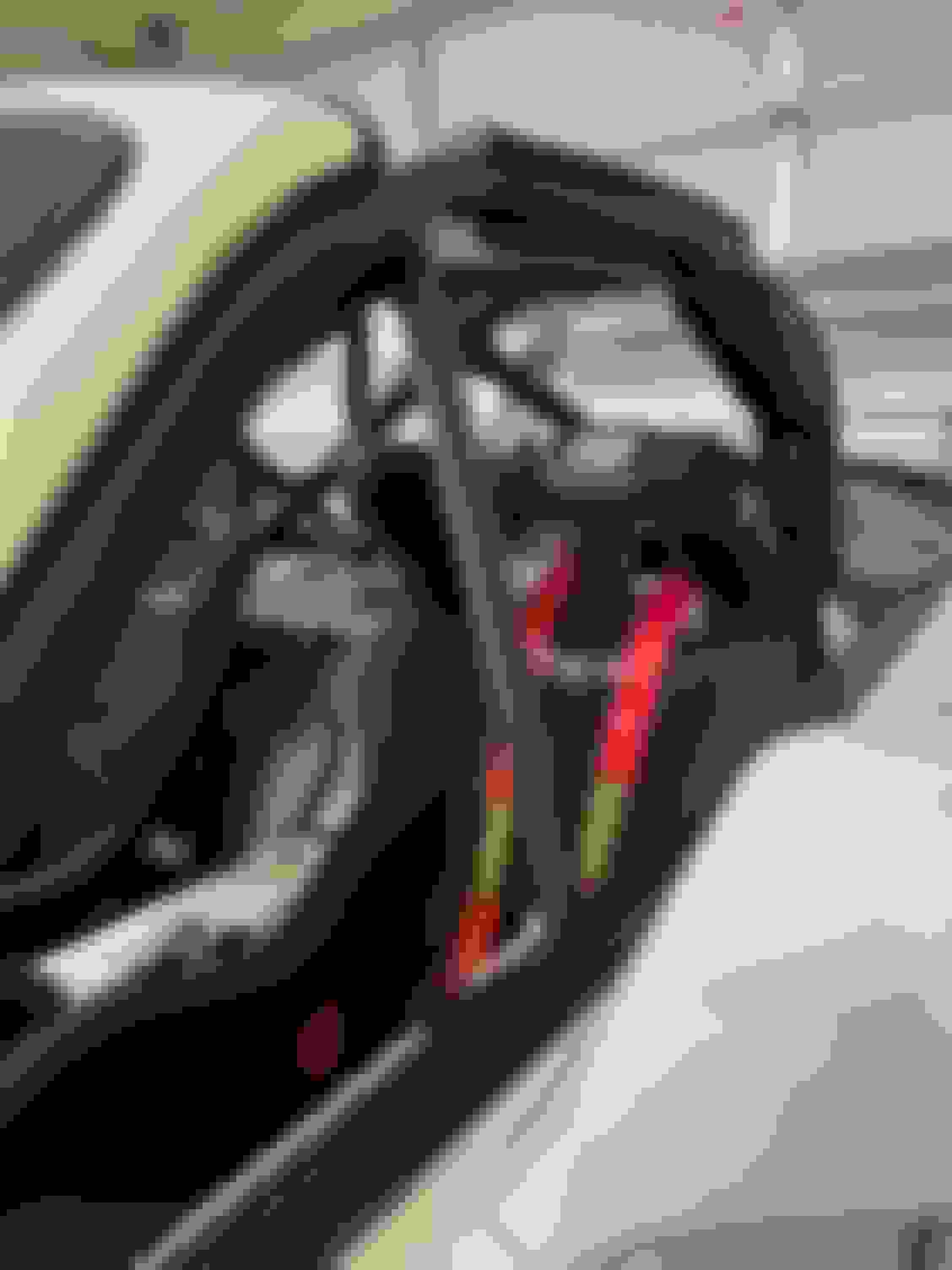
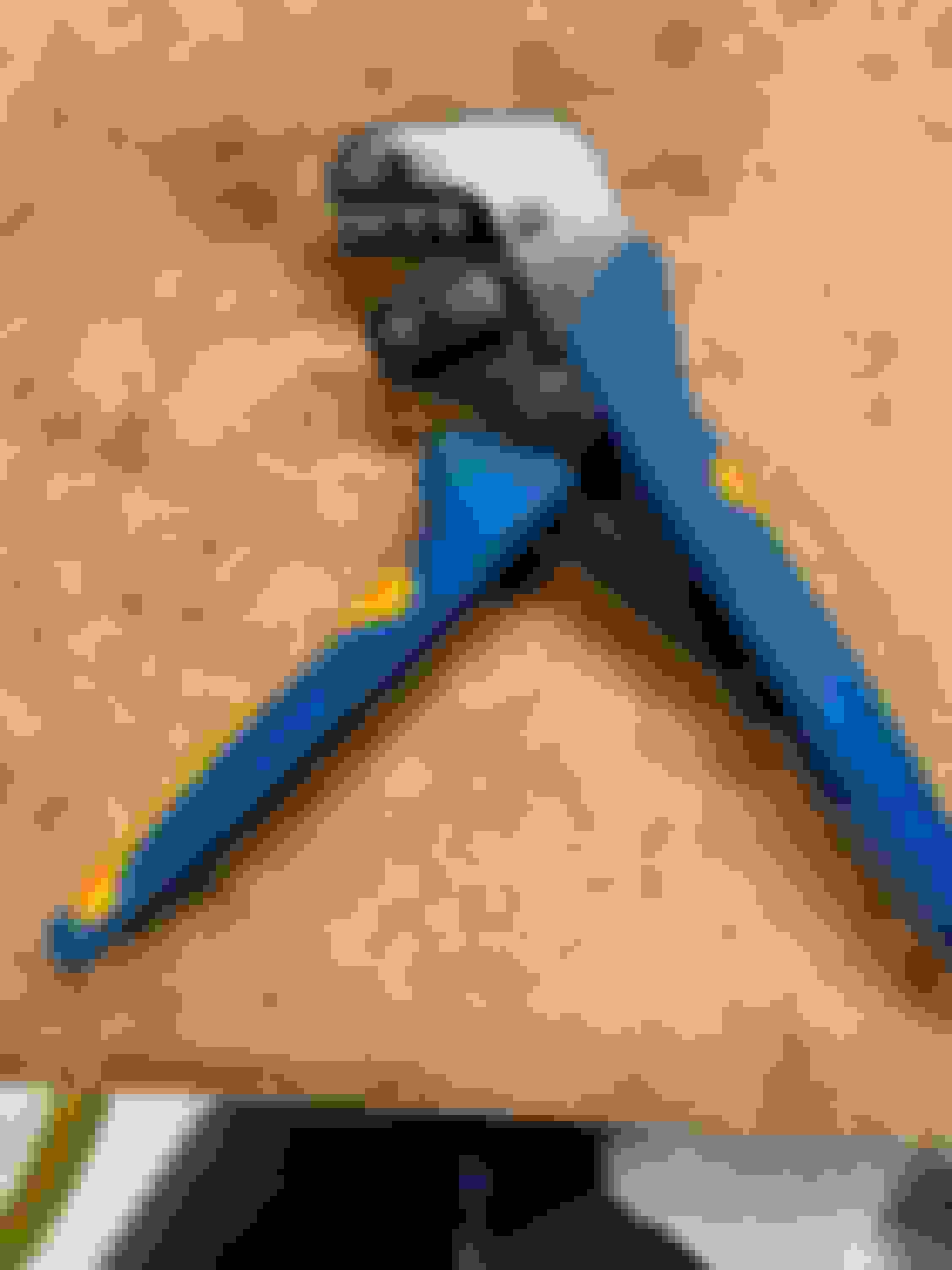
Then I added some red sheath I had left over from the door pulls for the handle. Figured that made it a little easier to “see” (Still need to trim off the end)
And installed in the trunk working perfect!
I also did the same with the trunk, although with the trunk I just used black for the handle since it was poking out of the car. I really like how both of these turned out.
Dead Pedal
The Dead Pedal wouldn’t fit with the cage bars, but I still wanted some place to put my left foot. I ended up taking a little off the top, so she would slide back in there.
Cut the top inch off and about an inch down on the support too using the metal band saw.
Here it is back in the car, with a better picture of why it needed to be cut.
Dash
The dash needed to be trimmed after the cage install for the front down bars so it would fit again. This took a few times of cutting and trying to place back in to see if it fits, after a few times I had her going back in relatively easily. The harder part was getting the few screws reattached under neither it. I probably should have take the bar out and installed it that way, but I was semi being lazy. I’m thinking this might need to be made to work with some quick disconnects, so easy to put in and pull out. That’s all for another day. I also need to touch up the paint where I cut eventually.
Crummy pictures, but you get the idea
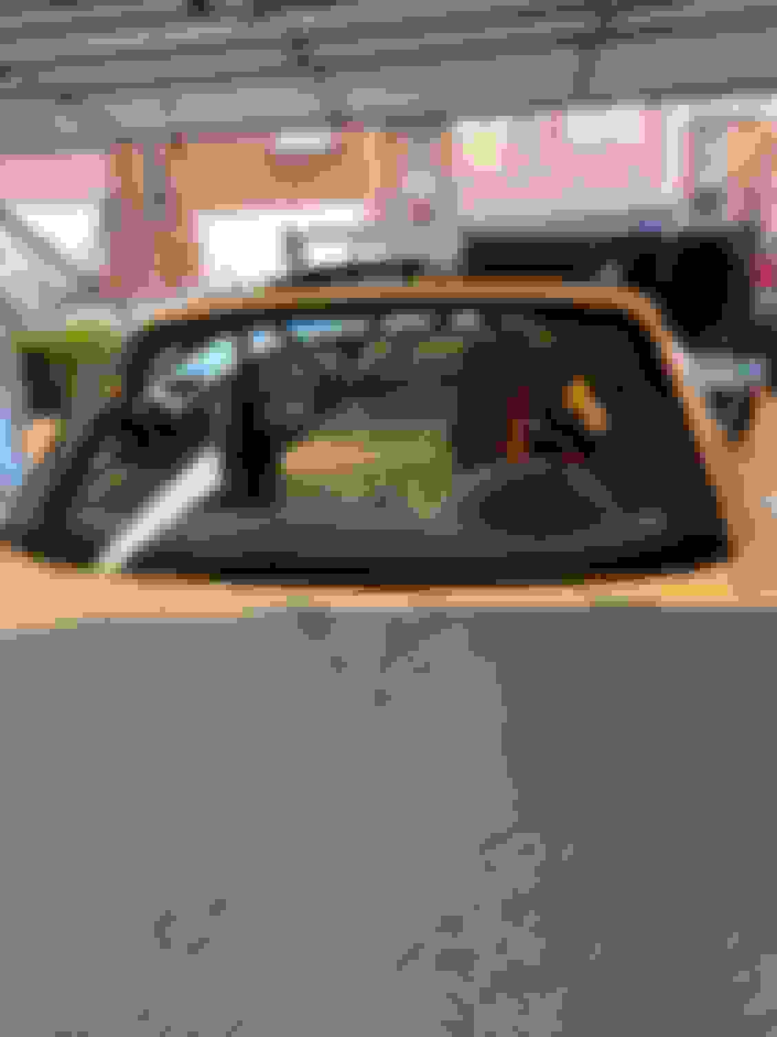
Windshield
For some reason the windshield seemed a bit intimidating. Now that I’ve removed and installed one, it’s really not that hard at all. The hardest part was actually removing the windshield (which I had already done beforehand to have the cage installed) Overall, I think I spent 50 bucks on the tools to remove & install and the urethane, primer, and new window trim. I didn’t take any pictures here (I should have, but didn’t think about it), but I mainly just followed some YouTube instructions (Chris fix was the most informative) and Voila! It went back in great. The only thing I ended up doing differently was the window trim didn’t want to sit on the window nicely. (It has a super shallow grove, but it wasn’t enough to hold it in place.) So I ended up using some painters tape and just taped the outside of the trim piece to the windshield so it was attached while I installed the windshield. The Urethane helps glue it in place.
I had a little too much urethane on the drivers ride. You can see it in the upper right corner and down close to the mirror. This wiped off with some mineral spirits while it was still wet. There is also two plastic blocks that hold the windshield in place at the base while it was drying. Not sure if those are OEM or if they were added by someone replacing the windshield in the past. For as much of a PITA the rubber trim piece was before installing...it looks great!
Rearview Mirror
This needs to be redone, but it’s working for now. I wanted the mirror pushed back a bit further. Where it was sitting when it hangs down was just going to get broken from my helmet / felt a little too close. Anyway, I used some aluminum 90 degree brackets that came with my Studi Boi kit that I guess NA miata’s need to use. Since I have an NB, I didn’t need them, and they seem to work fine at pushing the mirror back towards the windshield.
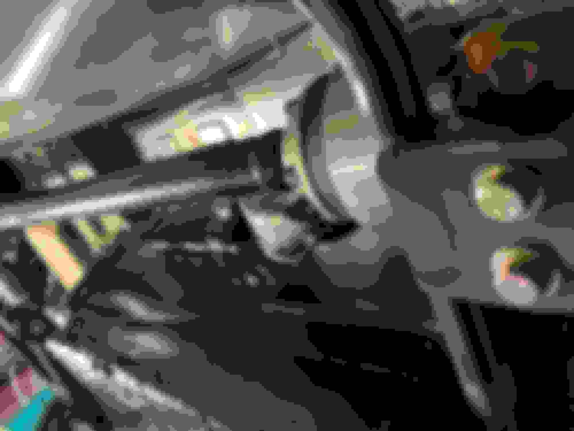
Picture is dark, but you get the way I have it temporarily installed for now.
Shift ****
Bought a new shift ****. I normally like a weighted ****, but I ended up going with the light weight racer version. It works great, and I don’t feel the need for more weight. The cool thing if I did want more weight, there is enough room after the threads to stick some weight into the **** if you really wanted too. So if your on the fence between this one and the weighted ****, I say go with this version and if it’s not heavy enough, its got room for you to carefully glue some weight inside it.
Sort of hard to tell, but there is room to add some weight in the there after the threads The hardest of all the installs! HA!
Front Fender Roll
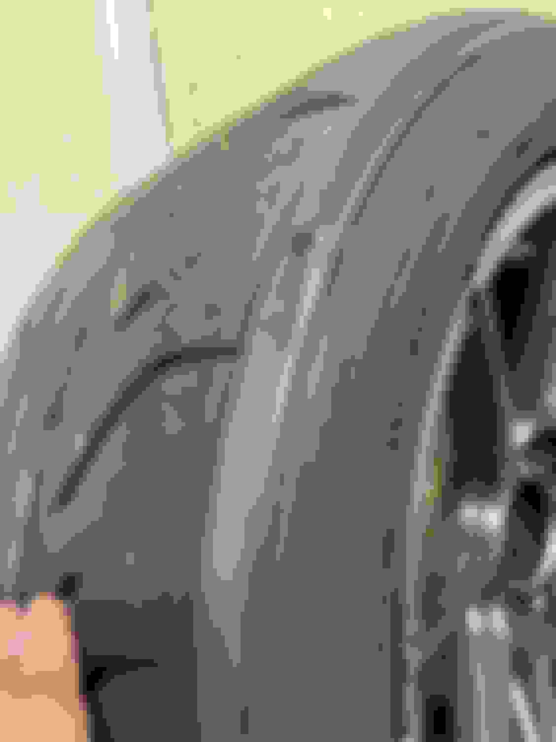
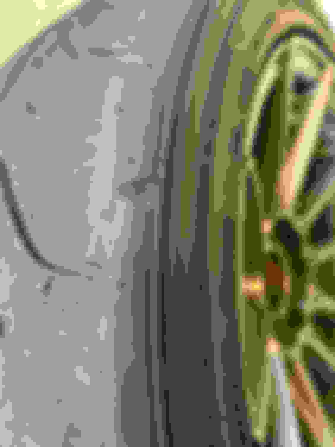
I didn’t really think I needed to roll the front fenders. Originally, I half assed did it and ended up just bending some of the tabs in. I thought that was job done, but I noticed that I was whittling down the sidewall on the drivers side tire. Not enough to need a new tire immediately, but enough that I wanted to fix the issue. The front fenders want to pull more then they want to roll…you sort of need to push against the fender as your using the roller to get it to actually roll vs pull. No pics of rolling the fenders, but here is one of the tire shave.
You can see the shaving the tire was getting... Here's the passenger side without any shaving to give a reference
Exhaust
With the Drop Floor being expanded out about an inch to allow my seat to be straight with the steering wheel, the exhaust was now in the way, so I needed to modify the exhaust to work. I just cut the one section out and rebuilt it, but to be 100% honest, the damn thing now has some blow by at the Vband and I need to work on this some more. That said, it’s not that bad and still under my local track’s sound limit of 98 db, since I didn’t get black flagged last weekend. I may just leave it as is at this point. The goal is to make this exhaust work for the rest of the year and I'll replace over the winter next year.
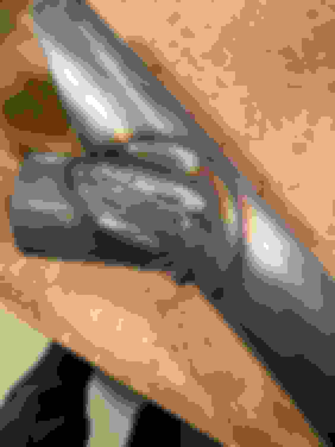
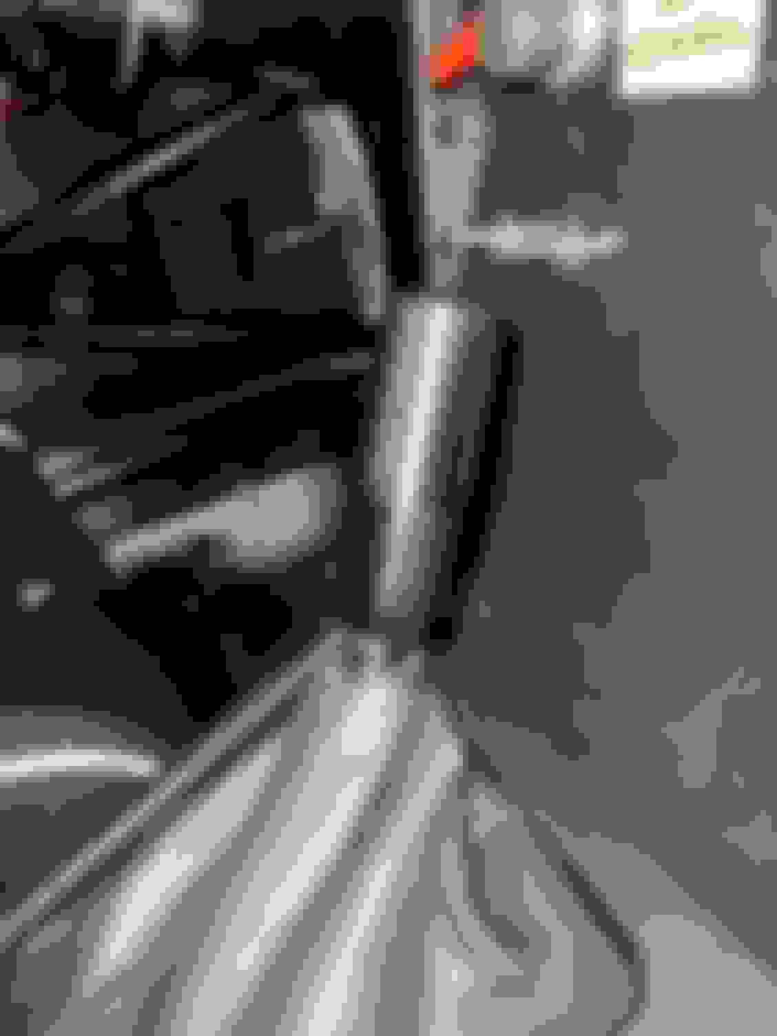
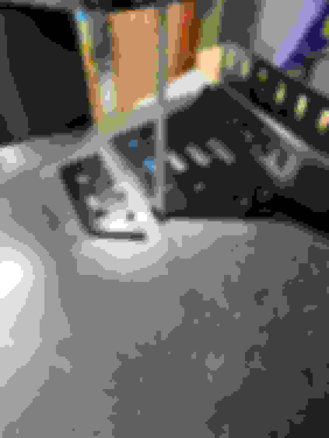
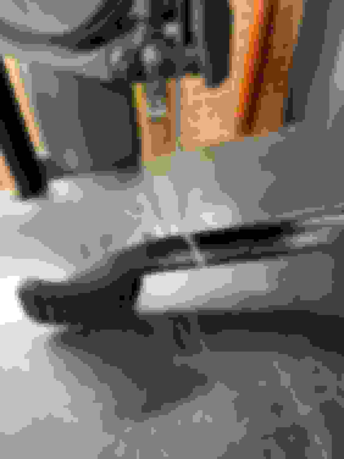
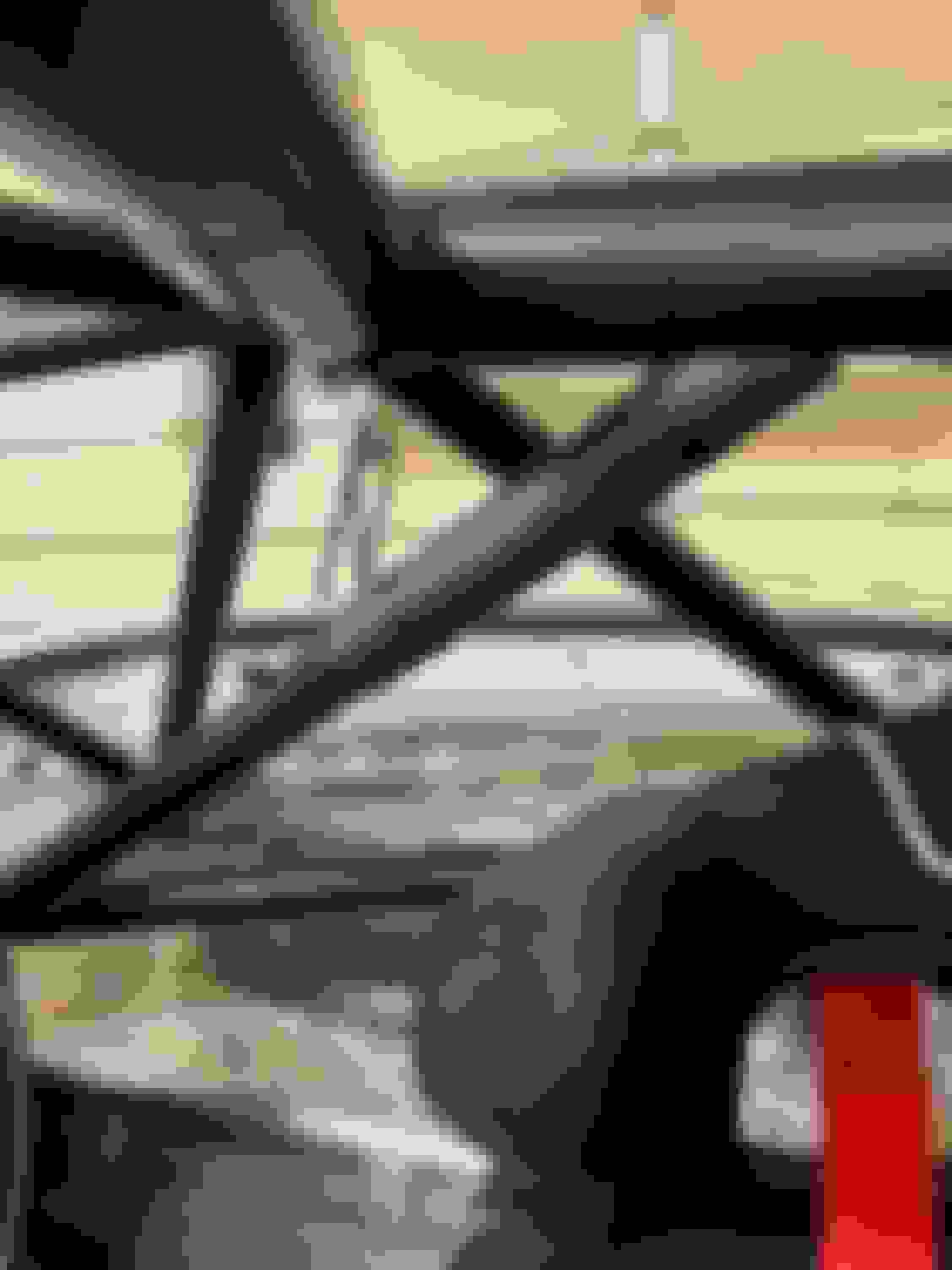
I cut it off at the Y and at the end of the small straight up that attaches to the flange
Here it is cut and starting to piece it back together again. This corner of the seat drop pan is the reason I needed to change it up.
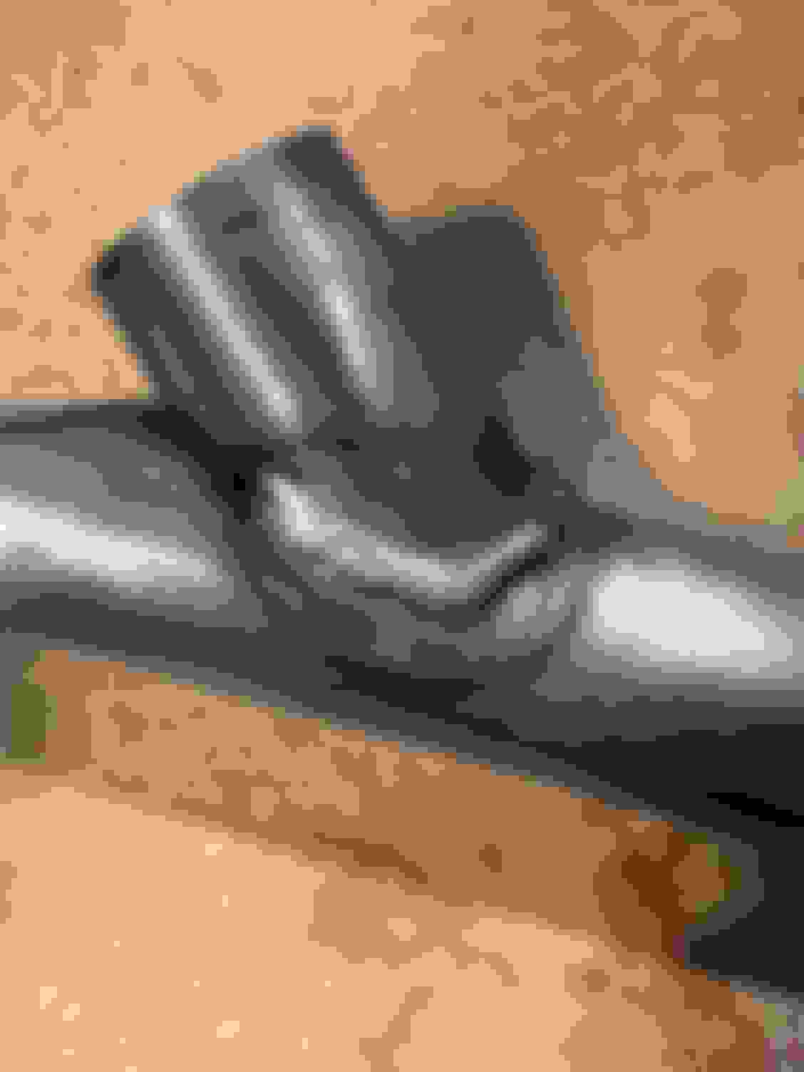
Here it is after the change re-welded up...still as ugly as before.
The above items are probably the “biggest” of all odds and ends. I’ll try and get the “safety” stuff written up next. It should be a smaller write up.
“Safety” was next on the list of winter projects and really just entailed installing the seats, harnesses, and roll bar padding. I’m always shocked at how long it takes to install all of this crap. I guess I think it should only take an hour and then I spent about a day doing this and that’s with a lot of the planning already figured out. Since I was running out of time, I decided to focus only on the drivers seat for now. I can install the passenger side at a later time.
Drivers Seat
First thing I needed to do was to make some backing plates for the seat mounts. So I ran off to HD Racing and picked up a way overpriced piece of steel bar. 2” X 4’ X 1/8” thick. I cut four 2” x 3” pieces off and then drilled a hole in the center of each that would fit an M8 bolt through it. Since this was going to be on the bottom of the car exposed to the elements…I pulled out a can of Rustoleum and gave them a quick coating to keep the rust off.
I made 4 of these guys...
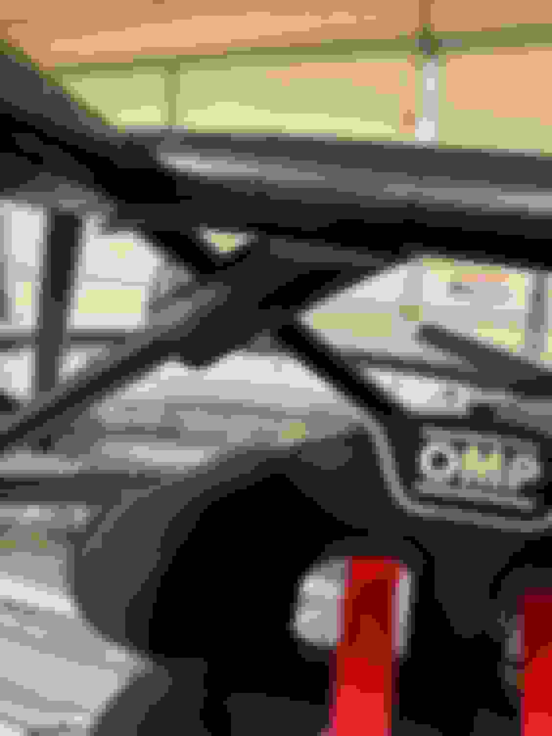
I had a real hard time finding seat mounts that would work. (I ended up buying 4 different mounts before it was all said and done.) I bought these because they were the tallest I could find, since the others where too short, and since they were OMP, I figured they would work with my OMP seat. Unfortunately, I still needed to modify these mounts because the lap belts wouldn’t have been able to go through the seat holes without rubbing on (and eventually fraying / cutting) the belts, which is a big No, No.
Even the OMP mounts with the OMP seat need to be modified!
So I ran them through the band saw and cut off an inch or so. After the bandsaw cut, I smoothed them down a bit with the angle grinder and then a quick hit of paint for the exposed steel.
And Voila, the finished mount cuts
I had already marked and pilot drilled where the bolt holes go in the floor, but they still needed to be enlarged, so I pulled out a step bit and enlarged them to fit an M8 bolt. I also drilled out the holes for the submarine belts. These are a bit wider then the approximately 4” apart that Schroth recommended, but the 4” mark put one of the bolts sticking out in the center of the support railing, which would have made it the absolute lowest part of the car and I didn’t like the idea how low it would have been. Way too easy to hit or scrape something.
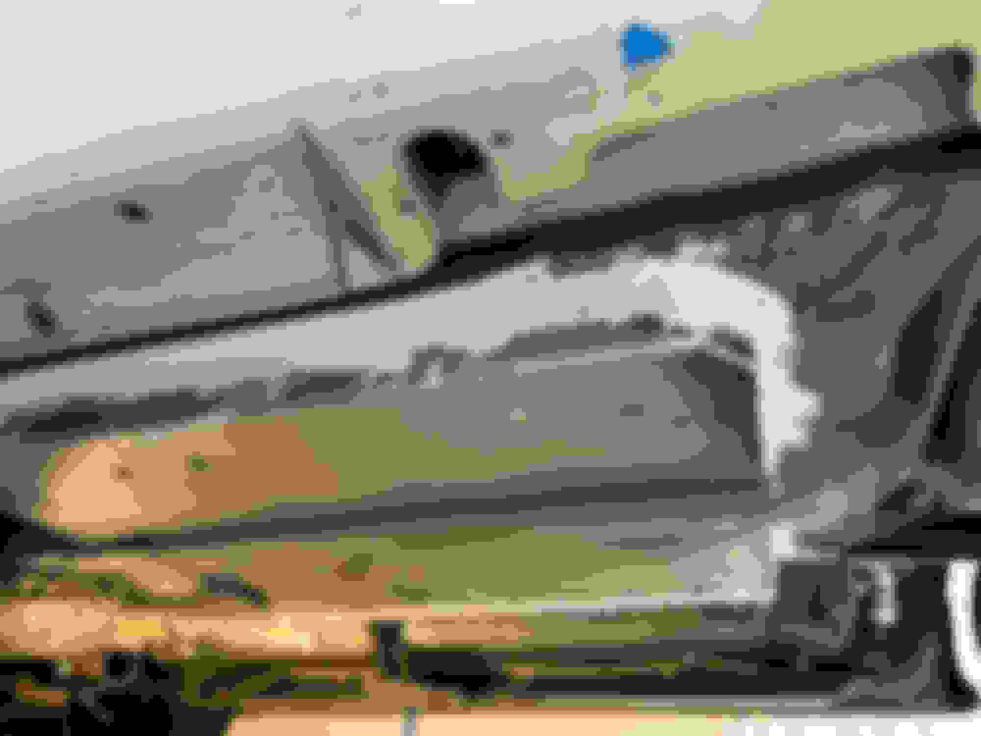
Unfortunately, I didn't take any pictures of this. Here is a crappy one peaking under the seat to give you an idea
I also modified the one anti-submarine belt’s backing plate so it would fit. (again, the bandsaw to the rescue and cut about a 1/4” off the side). This picture makes it look like I cut a bunch more off it. You can see the pilot hole of where the "ideal" spot would have been that I originally drilled too.
The two sides bolt holes were already in place from the cage install, so I screwed in the eyes for the lap belts. (Super easy!)
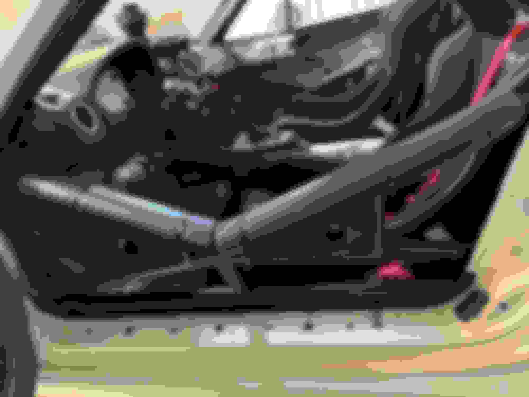
I realized I was going to have a challenge getting the rear bolt next to the door in place due to the cage. So I decided to tack weld it onto the bracket. This way I no longer needed to hold it in place while tightening the nut from underneath.
Here it is from underneath all put together. These bolts are 25mm, I’m going to probably change them out to 20mm later. Also need to get better lock washers. I thought I had some that were large enough, but these aren’t as large as the flange of the bolt…so I’ll be replacing these at a later time too. This worked to get me on the race track.
Harnesses
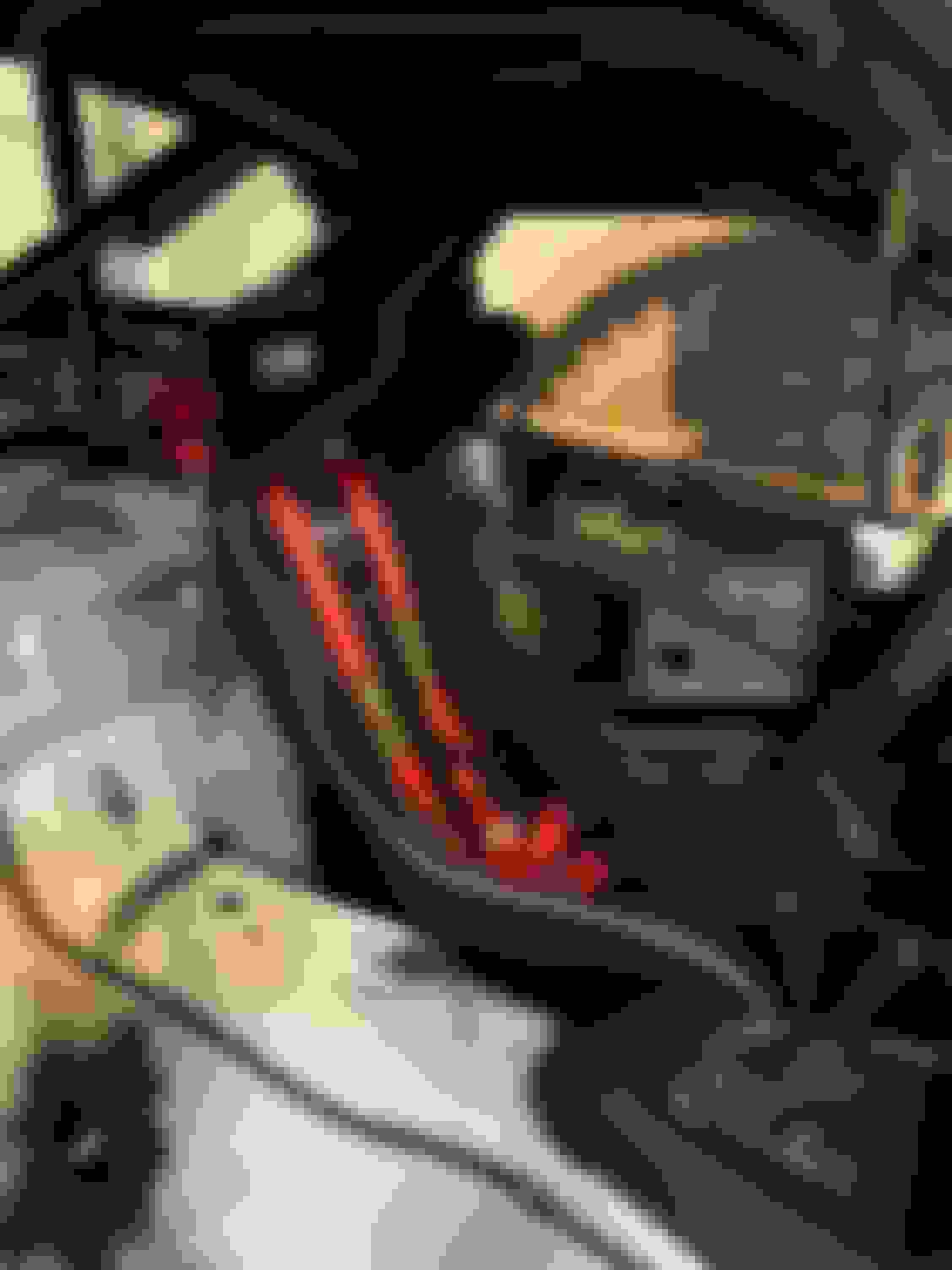
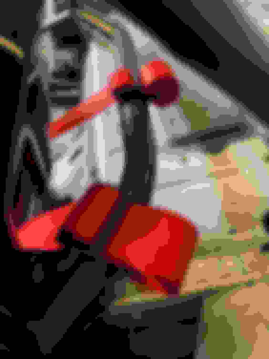
My old Racequipt harnesses were always a pain in the *** to adjust. I had a hard time swallowing the cost, but I wanted belts that adjusted easily, and the Schroth harnesses immediately showed why they cost so much (and why people like them so much). They were so easy to mount. Super easy to even wrap the harness through the 3 bar slide. I remember doing this with the Racequipt belts and taking forever to thread the harness through the slides, needing needle nose pliers to pull the very first part through. The material on the Schroth is much smoother like a car seat belt and it makes all the different in the world. Looping it through the slides was almost too easy. The other parts were just as easy too. They just hook on, the hardest part is putting the cotter pin in them. I still have a little adjusting to do to make them fit without huge tails, but it works for now and was super easy to install.
Here it is all installed
Shoulder harnesses installed.
Roll Bar Padding
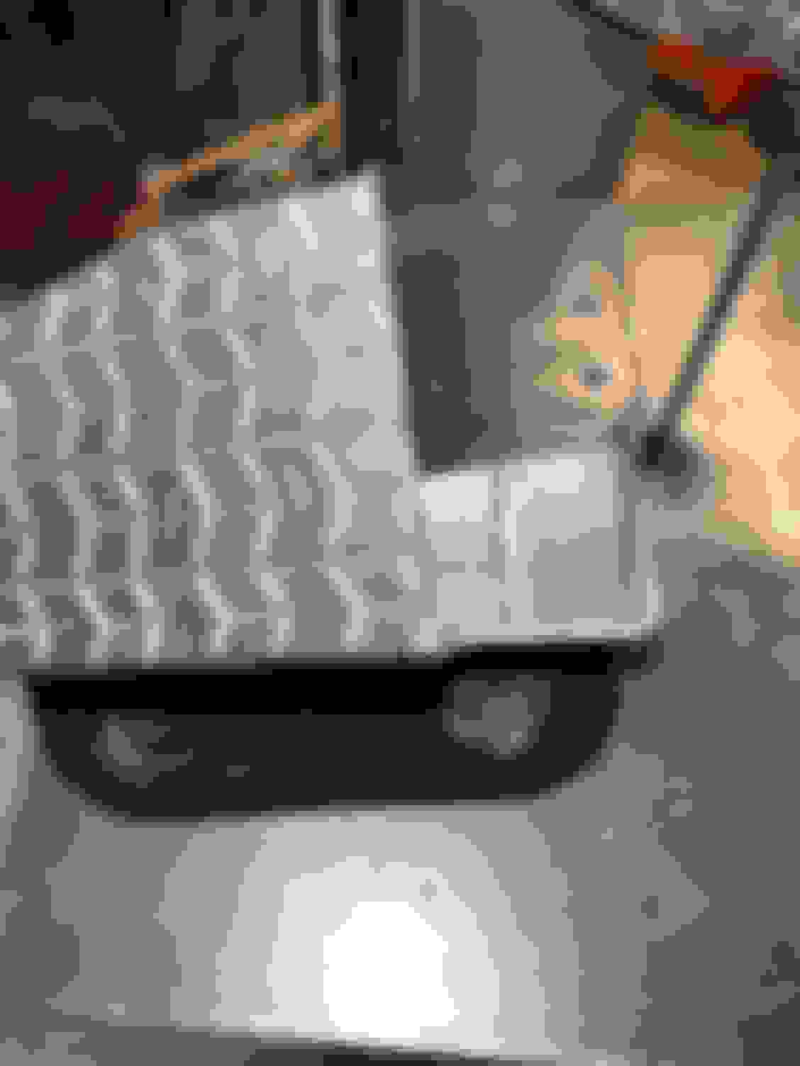
I bought a few different sizes / sticks of padding. All of them are SFI padding (no pool noodles) but some are a little thiner or don’t wrap all the way around making the side profile smaller. Previously I was just cutting the padding with a hacksaw. It left the ends a bit rough and crumbly. I had the bright idea to use a hot knife, thinking this would melt it to be nice and clean. If your a little brighter then me, you already know where this is headed. The hot knife does cut the padding, but it doesn’t melt nicely like I was hopping. Which is one of the defining characteristics of SFI padding, that it doesn’t melt all over you. LOL Anyway, I found that a palm sander does a very nice job of smoothing things and not looking like I used a butter knife on it. I still need to install padding on the door bars for my arms. At the very least my head is protected now.
Notch cut out of the padding with a hacksaw...all crumbly
Here it is after 15 seconds with the palm sander
And cause I was awful at taking pictures during all of this (I was really pressed for time doing all of the work in this post). This is the best picture I have of the padding installed
After the padding, the top doesn’t fit down all the way in the back, but I could bolt it all down. Not ideal for a street car, but works fine for racer. I can also go back and try and fix some of the padding to work with the top better.
As good as it gets for the first track day of the year.
I still need to put the passenger seat in, but I was out of time to be ready for the first track day of the year so that’s to be done at a later date.
You can trim the padding, but I am not a fan of that and the scutes may give you a hard time. So ...
Take the top off the rear mounts, you can access the Frankenstein bolts. Remove them, remove stud from fitting, insert longer stud to suit. Just make sure your HT is sealing against the body or the water will get in.
I trimmed the very top of the padding where the top hits it. (i.e. where my body will never touch anyway, or if it does...that means I've been ejected from the car & either dead or will be momentarily.) I'm not using the Frankenstein bolts (I have it bolted in at the top and the sides, my understanding is most don't use the Frankenstein bolts if you bolt them in like I have. The good news is that its actually fitting better once I removed it and put back on, but either way, I'm not worried about it. It's a race car and lives in the garage. It won't see enough water to be an issue.
I'm going to skip ahead a bit. (Skipping over all the aero changes I made this winter...I'll write those up next, but this is fairly fresh in my mind right now. My first track day was March 19th, what I think might have been the coldest day of the year in Atlanta so far. It was below freezing when we first went out on track and warmed up to a balmy 42 or 44 degrees by the end of the day. Brrrr!
Anyway, the goal for the day was more of a shake down of the car after all the changes I made since August of last year and to reacquaint myself with AMP. First time driving AMP in this car and a couple years since I've been there.
I drove 4 session and had a great time, the last session especially. This car is SO much better with it's handling. It doesn't push everywhere or ride on the bump stops like my old miata. It's such a pleasure to drive!
That said, I did walk away with some items that needed to be addressed.
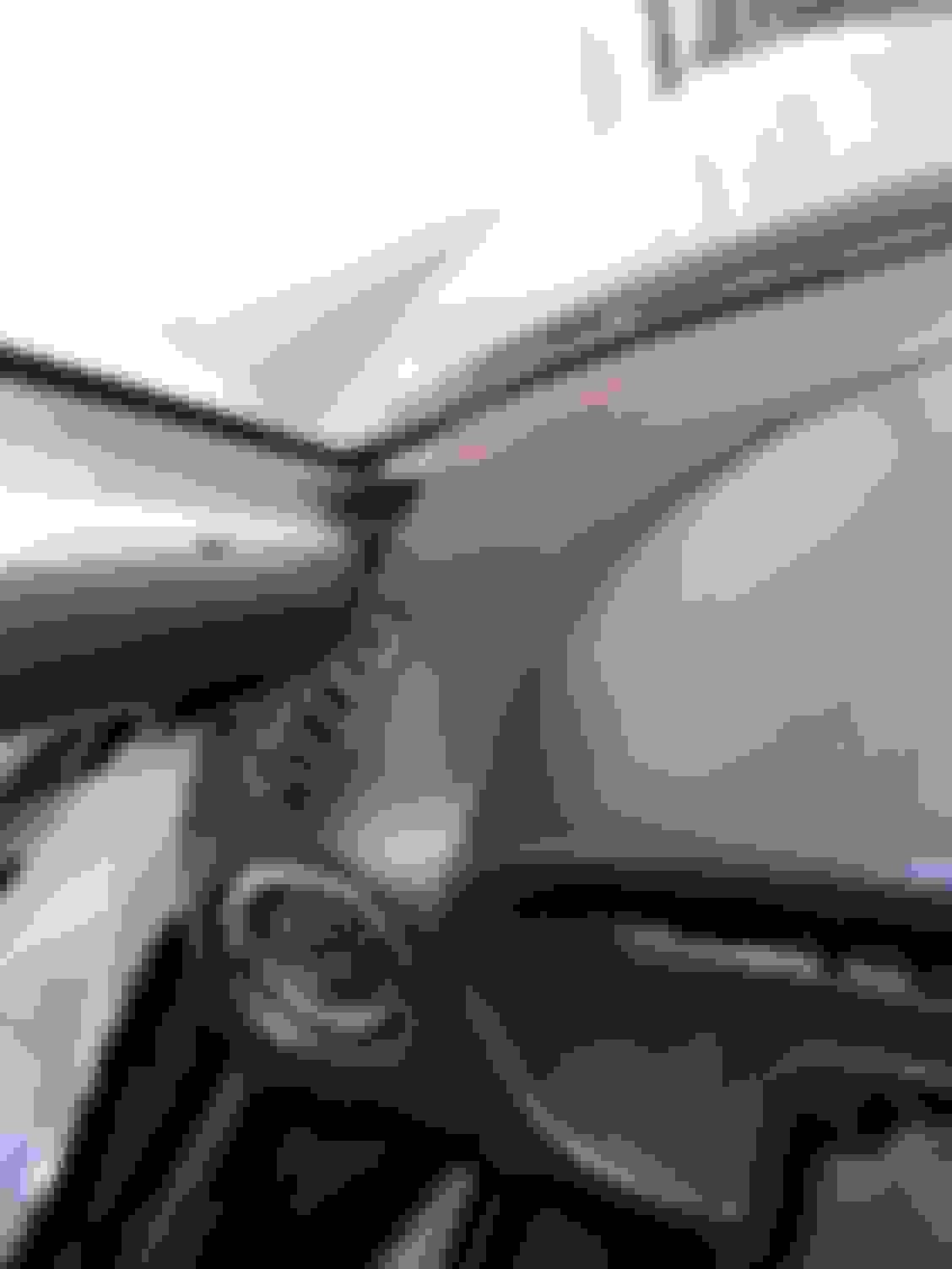
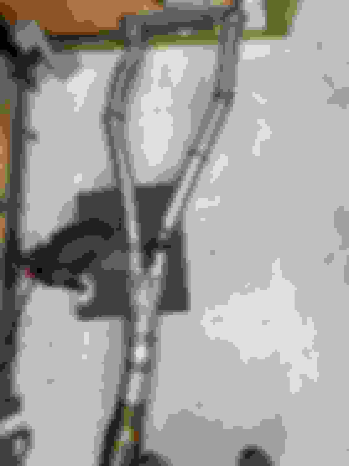
Clutch Pedal So the first and biggest issue with the car, is that my left foot doesn't fit. It gets caught between the clutch and the dead pedal. This made shifting the car a very sketchy endeavor!
As you can see...my foot gets caught. (To make matters worse, I have wide feet and these are "wider" when I'm wearing them)
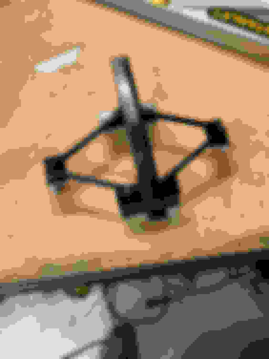
I decided to move the clutch pedal over an inch. The steel is very thick on the clutch pedal, (about 3/16" or 5mm for the civilized) and there was no way I was going to reach down there and just bend it. So out the pedal came for some modifications. I cut it here because it was a semi straight section and figured easier to get the pedal reattached straight.
I used some 3/16 thick scrap bar and made a piece to add to the pedal. I had to get creative with holding things in place to weld it all up.
Test fitting and realized that I cut the pedal too low. Oops! Although I really like where it's gonna end up.
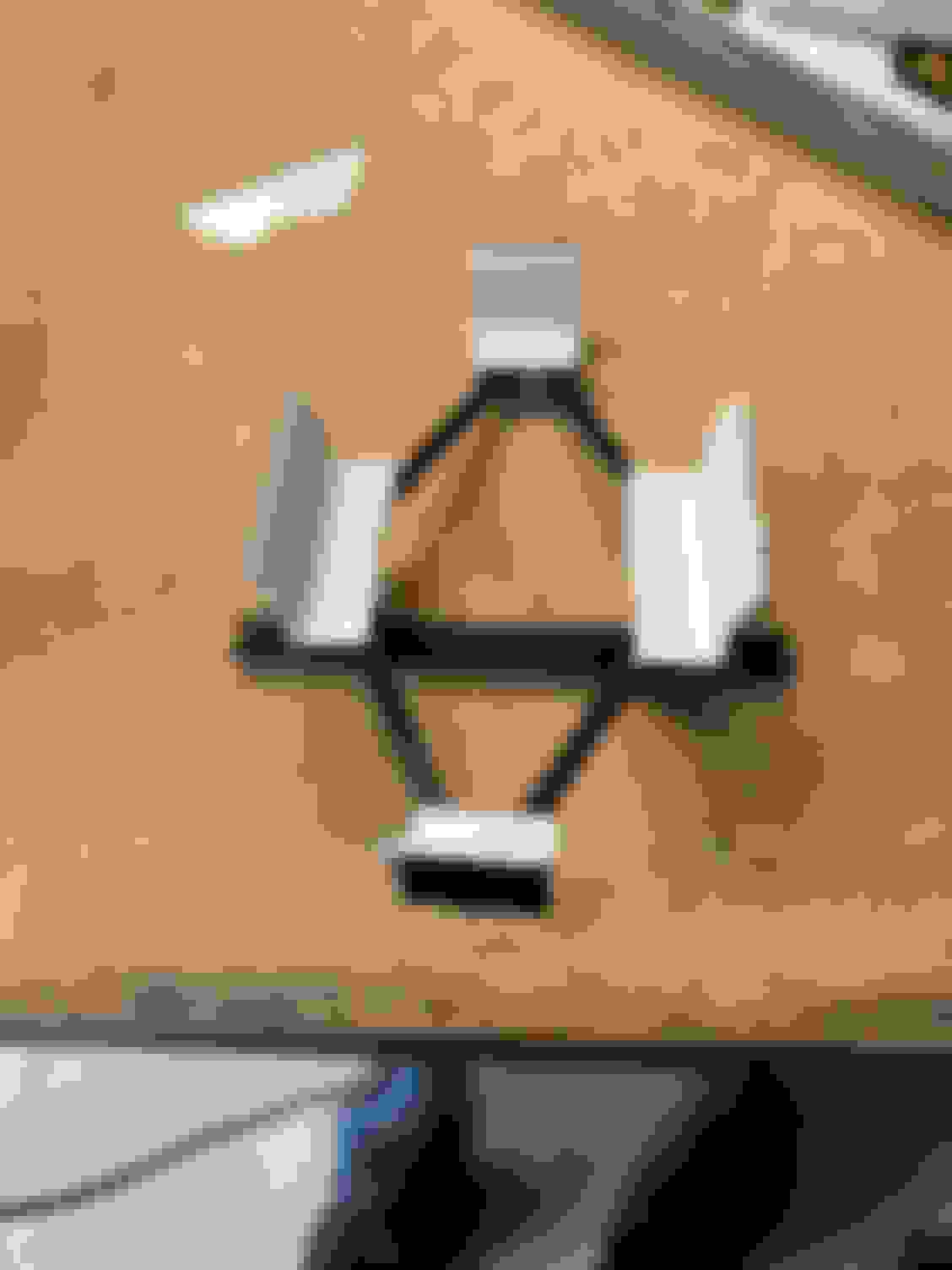
Welded her back together...so I can try again. This time much higher and it works great! Plenty of room for my foot and still enough room between it and the brake pedal! Although that stud (still in picture below) attached to the firewall was just barely an issue now. So that had to go too. Picture below this one shows it gone.
And here is the final result after painted and such. Not the prettiest, but functions well. (BTW...This worked great. Shifting is easy again! I can't tell that I moved it expect that my foot comes on and off the dead pedal without hitting the clutch now.)
Harness
The shoulder harness kept sliding over to the one side due to the curve.
So, I bought some collars and now it stays where it's supposed to be
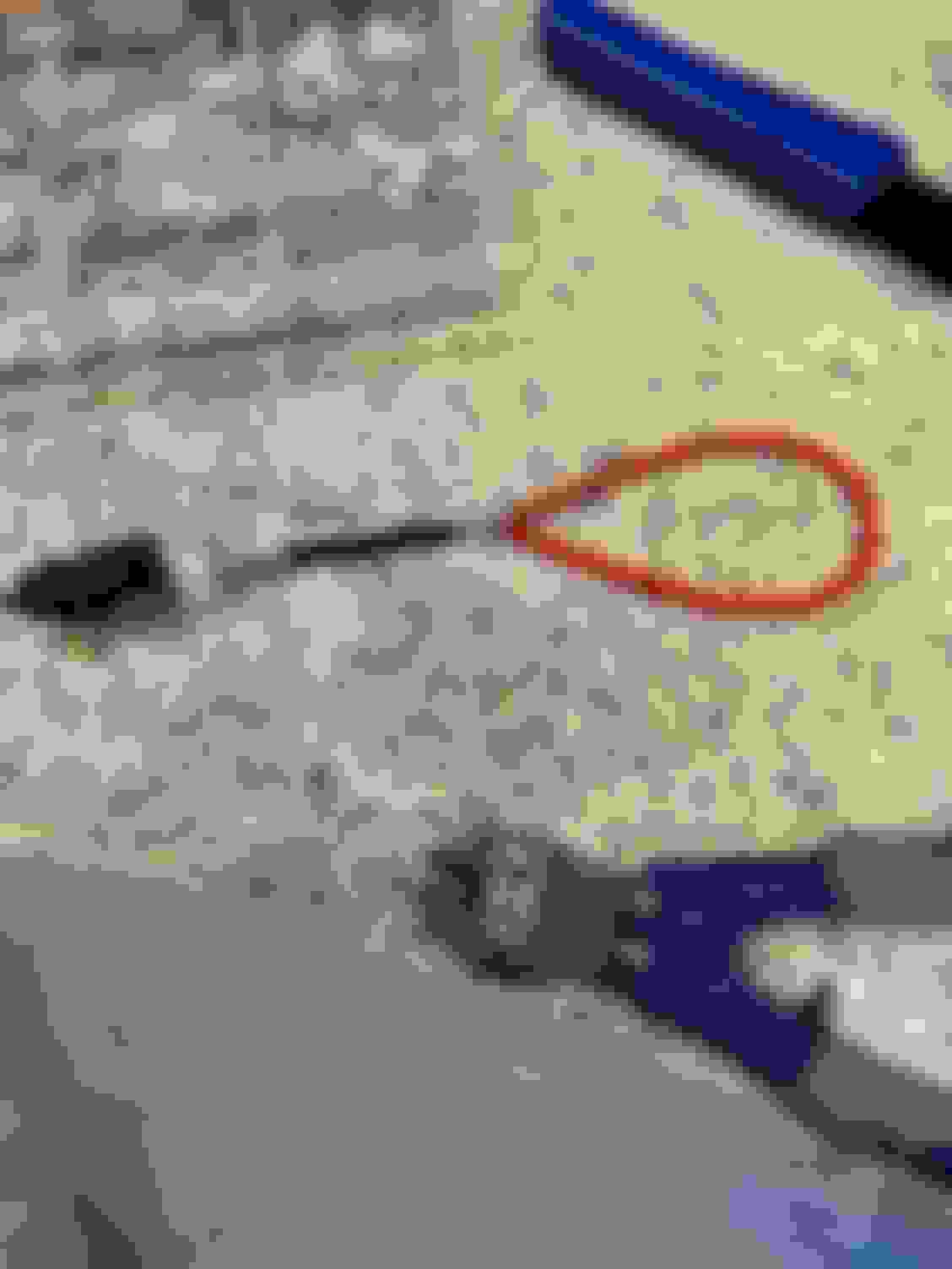
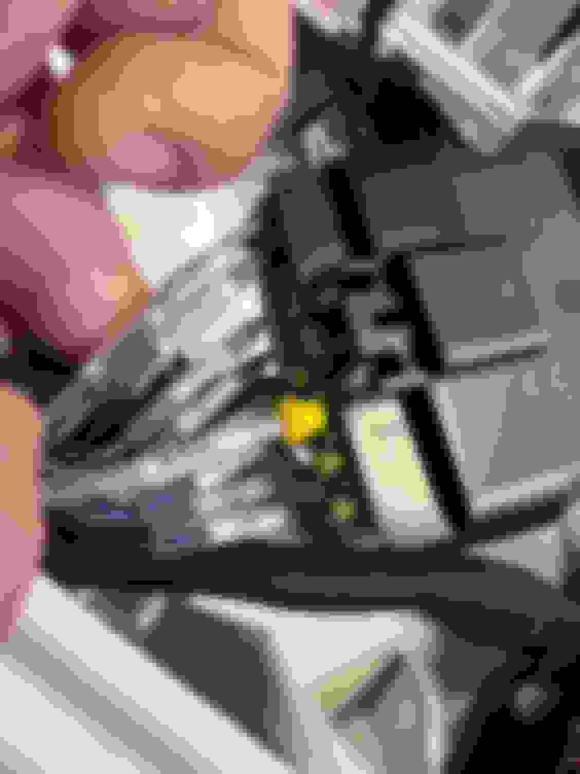
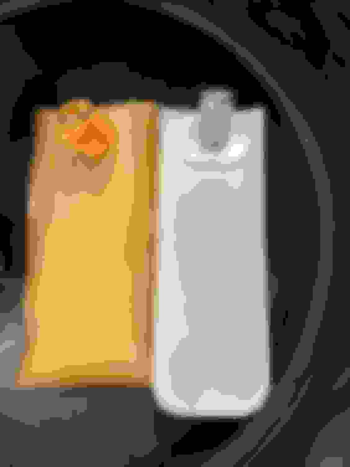
Electrical I went to get in for my 5th session of the day and the car wouldn't start. I noticed that the fuel pump wasn't priming / turning on, and quickly also realized that I hadn't labeled my fuse box / relays like I planned on doing. I was hungry and decided to eat lunch and then figure out the issue. Funny enough someone stopped by to look at the car and was asking about how hard it was to do the wiring and as I went to show him the harness the fuel pump wire popped out of the connector. I would have never found this so easily if it wasn't for me showing this guy. Anyway, I did a makeshift crimp on it and that got the car running. Once home I crimped on a new terminal and fixed this issue properly.
Nothing to really see here. The yellow seal sticking out is how I left it after the makeshift crimp at the track. It's now properly crimped and seal in place correctly.
Tires Someone was really enjoying all the power the LFX has over the stock BP and came in a little hot on the front straight for such a cold track. I ended up locking up the front right tire and barely missing taking a trip to the beach on turn 1. It was all fun and games until that happened and I had a square tire that was showing cords. The quick fix is a new tire, but ultimately, I need to get ABS installed on this car. This isn't the first time (or last) I have made a square tire.
I never took a picture of this, but I feel confident most of you miata track guys have your own collection of square tires.
Seat I'm not sure if my left leg was hurting from not being able to get between the pedals or if I was still too close to the pedals. To push the seat back, I also needed to go a little lower, so the seat would work with the door bars. Unfortunately, the bottom of the seat would touch (just enough to keep you from barely bolting things in if I went lower. I decided to make some spacers out of 1/8" thick aluminum. This raised the seat up 1/8" but going down a notch on the mounts lowers you 3/4" so overall I'm 5/8" lower. (I'm also now half an inch further back.) Happy to report this is perfect distance for my legs and I'm really happy with this change.
Here are the 4 spacer marked and ready to drill the hole for the bolt to go through. (I know...super exciting picture here!)
Here's one you can see, between the seat mount and the floor.
Hard to tell in a picture, but this seat is sitting pretty now now!
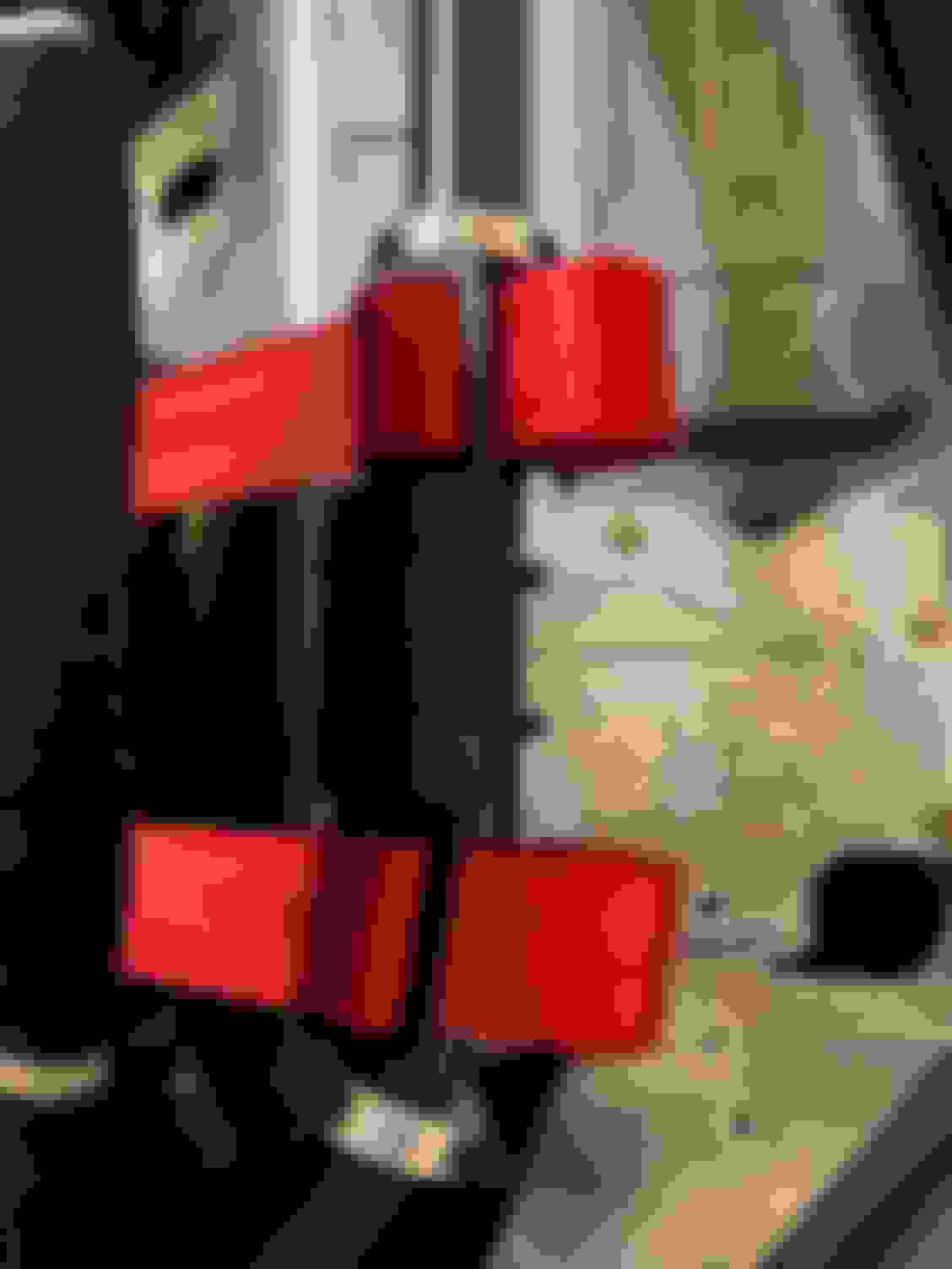
Padding I also added padding to the door bars. Hopefully my elbow or arm never touches any of this in an accident, but this might make me go from shattering a bone to just breaking one if I'm in a bad accident. I actually cut about 1/2" off from the padding where the tacos are. This allowed me to rotate the padding a bit more so it covered the bar better for my arms.
These will probably need to be replaced once a year or so with getting into and out of the car
I also put a thinner piece of padding on the diagonal bar. The original piece I had installed was oddly enough blocking a lot of the view from the rear view mirror. This gave a little more visibility behind me.
Barber Motorsports Park April 10th These changes had me all set for my trip to Barber. The car did great at Barber. I only have two items on the punch list before the next track day.
Another Tire First, I need to swap another tire. I was getting vibrations (like I had flat spotted another tire!) and realized I had another issue. This tire was previously on the rear of the car and looked a little suspect when I rotated it to the front, but showed it's real colors after spending a day on the front of the car. I had a couple people come up to me with their stories of the RT660 delaminating on them. That sucks, I was hoping this was a one off issue...I'm a fan of cheap and sticky tires.
This is after the tire has cooled and somewhat stuck back to itself. It was super noticeable in the pits after I got off track with the tire hot.
Steering Wheel Spacer Second, I need to get a steering wheel spacer to move the steering wheel a little closer to me now. I noticed when turning that I was reaching a bit and I think moving the wheel a tad closer to me will be the last piece of the puzzle to be "comfortable" and safe in the car. I went out to Amazon MotorSports and bought this 2" aluminum spacer
And here she is all installed.
All and all, I'm pretty comfortable sitting in the Miata now. Actually, this is the most comfortable I've ever been seated in a Miata...I think I could drive a couple hours and feel fine. So I'm gonna say I've meet one of my original goals of making the car comfortable to be in (since I was never able to get that comfortable in my last car with my legs too close to the pedals etc.)
Re clutch pedal, I would have raised the footrest first. This is something that troubles me too, but not to such an extent that I have actually felt the need to do something about it - it just seems like having the foot level with the pedals would be 'a good thing', especially if you are a left foot braker.
Re clutch pedal, I would have raised the footrest first. This is something that troubles me too, but not to such an extent that I have actually felt the need to do something about it - it just seems like having the foot level with the pedals would be 'a good thing', especially if you are a left foot braker.
I like the idea & I tried that with a block of wood. It was uncomfortable. My ankle was bent too much / leg too close to me. Thus why I also moved the seat back too. In the end, I spent about half a day to remove dash & pedal, modify (twice with the screw up) & reinstall all of it. So not that big of a deal.
I keep working on and driving the car. Just behind with the blog some. I'm gonna try and get a few more posts out in the next month and see if I can get semi caught back up.
I was super exited to finally get my AIM PDM32 kit after waiting 10 months. Although the Torque Pro app and elm 327 wireless OBD2 worked surprisingly well for gauges, I was using the cheapest Wally World tablet you could buy and it would wash out in the sunlight or turn totally black when wearing my (polarized) sunglasses. With a better tablet, you could definitely make this setup work for you.
Since I wanted to know my lap times and wanted gauges that I could actually see, I tried to quickly install the AIM PDM32 in the most minimal way to get the functions I needed immediately. In other words, connection to power, ground, ECU, Screen, and GPS unit. I’d leave all the “PDM” stuff alone for now and continue to use my fuses and relays that I already had wired up.
Before I get into how I set mine all up, some items I wish I knew up front. (Most of this is a complaint) Since there is very little info / reviews on these kits.
1. Instructions are beyond lacking. The manual is 63 pages short and what little that is written isn't written very well.
2. The AMP connectors AIM choose for the PDM take a wire size of 20 - 16 gauge. The issue here is the PDM has channels that handle both 20 & 35 amps continuous. AIMs solution is to have you run two 16 gauge wires to handle all of that power. Needless to say, I'm not impressed with this "solution".
3. On the subject of the AMP connectors, a normal hand crimper isn't going to work. (I tried) You're gonna need to buy a fancy $300 crimper for those connectors. AIM makes certain of this because they use 22 or 24 gauge wire for their CAN bus that the GPS, Smartycam, Keypad, etc. use. The $300 crimper does crimp the tiny gauge wire and it holds, but it's an ugly crimp. I couldn’t get a generic hand crimper (same one I used for every single crimp on all of the other wiring on the car) to work.
4. You're going to have to wire up an on / off switch even if your using the AIM CAN Keypad (I was hoping to just use a single keypad for everything.) The keypad only works if the AIM PDM is already on.
5. The 10" screen only has 6 layouts to chose from. You can only use these layouts, but you can change what items you want to show on the layout. (i.e. Oil Pressure, Volts, Coolant Temp, etc. can be placed in any of the 6 or 8 spots, but you can’t move the spot or add additional spots)
6. The screen is thick like over an inch and she's got some weight to back up that thickness. More like it’s from the 90’s vs today. On the positive side, it seems super sturdy / you could probably run it over and it would still work.
7. You're going to need to buy more AIM “parts”. This is really just a starter kit. For example, you need to buy either a CAN Keypad for your switches, or another device (Rio02) that allows you to wire up your switches. Want to add a sensor? You need to buy a CAN Data Hub to connect it.
8. You need a windows laptop or an older Mac laptop with an intel chip that you can install windows on to run the AIM software.
9. The RaceStudio Software has an AWFUL interface. Something I would expect from the late 90’s designed and build by developers, but they skipped the UX designer. The Software seems to work well, but it’s not easy to intuitively use it. (It is pretty powerful the more I learn to use it, the I realize it allows you to do. BUT you're going to have to watch a ton of youtube videos to learn how to use it.
10. My ECU does transmit data on the CAN bus to the PDM, but all of the inputs for things that I want to use the PDM for as fuses / relays don’t come across the CAN, so you still have to wire up all those inputs. I was hoping to not need to wire up that side, and capture from the CAN message when to start the fuel pump, or turn on the coolant fan. Not a huge deal, and you could find work arounds to code this without using the ECU if you really wanted too, but that doesn’t simplify the wiring as much as I was hoping for. FYI...Your ECU may send these messages across, but I know the Chevy one doesn’t.
Alright, enough with the complaining...onto the install.
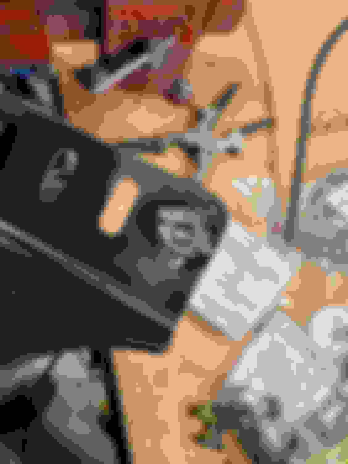
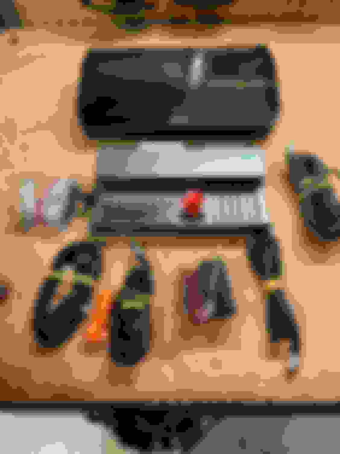
You get two boxes…and all of the following is inside (note, the GPS unit is on the right, and I didn’t take a good picture, since you only see the wire, not the unit)
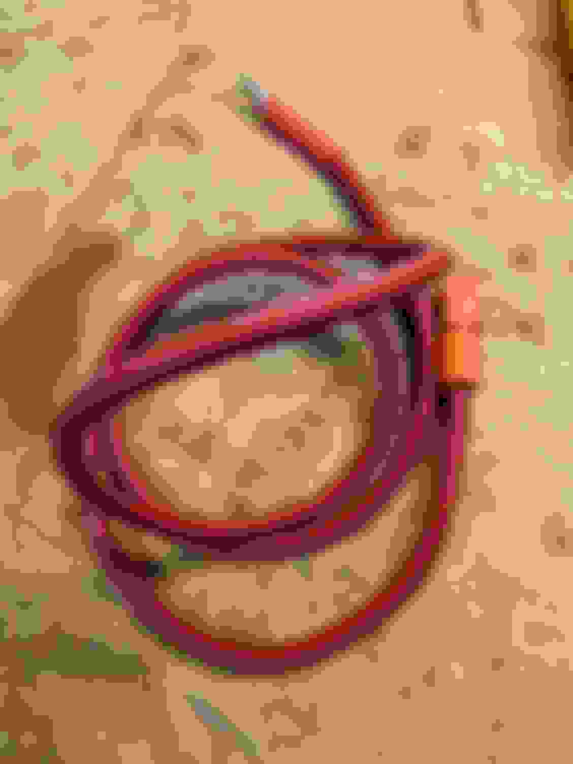
I started off the install process with getting the wiring ready. The main power in wire needs to be 4 gauge. You maybe able to get away with 6 gauge. That orange connector end comes with the PDM. You have to crimp on the connector. The plastic piece unscrews off and you then have a spot to crimp the wire. I only took a picture when I was done making the wire. This wire will go from the kill switch to the PDM.
I also wired up the on/off switch for the PDM. I was able to hand crimp the 20 gauge wire, but I will admit, it was ugly. I may wire this up to the kill switch using it as the on off in the future, but for now I can switch it on and off separately
Then I wired up the AIM CAN connection for the GPS. This is where I hit my first snafu. For the life of me, I couldn’t crimp on the CAN wires for the GPS. The wires they used are definitely smaller then 20 gauge. The “big” wire is TXL 20 gauge wire. The small wire is the CAN wire that AIM supplies.
I did some research and found an AIM PDM group on Facebook. I guess others have tried like me, and were also unsuccessful. Anyway, here's a picture of the ridiculously expensive crimper your going to need.
Probably because I was irritated at the whole thing, I never took any pictures of the ugly crimps etc. After the AIM Can, I added two ground wires for the PDM (both 16 gauge wires) and ECU Can wires. Then I was done with wiring.
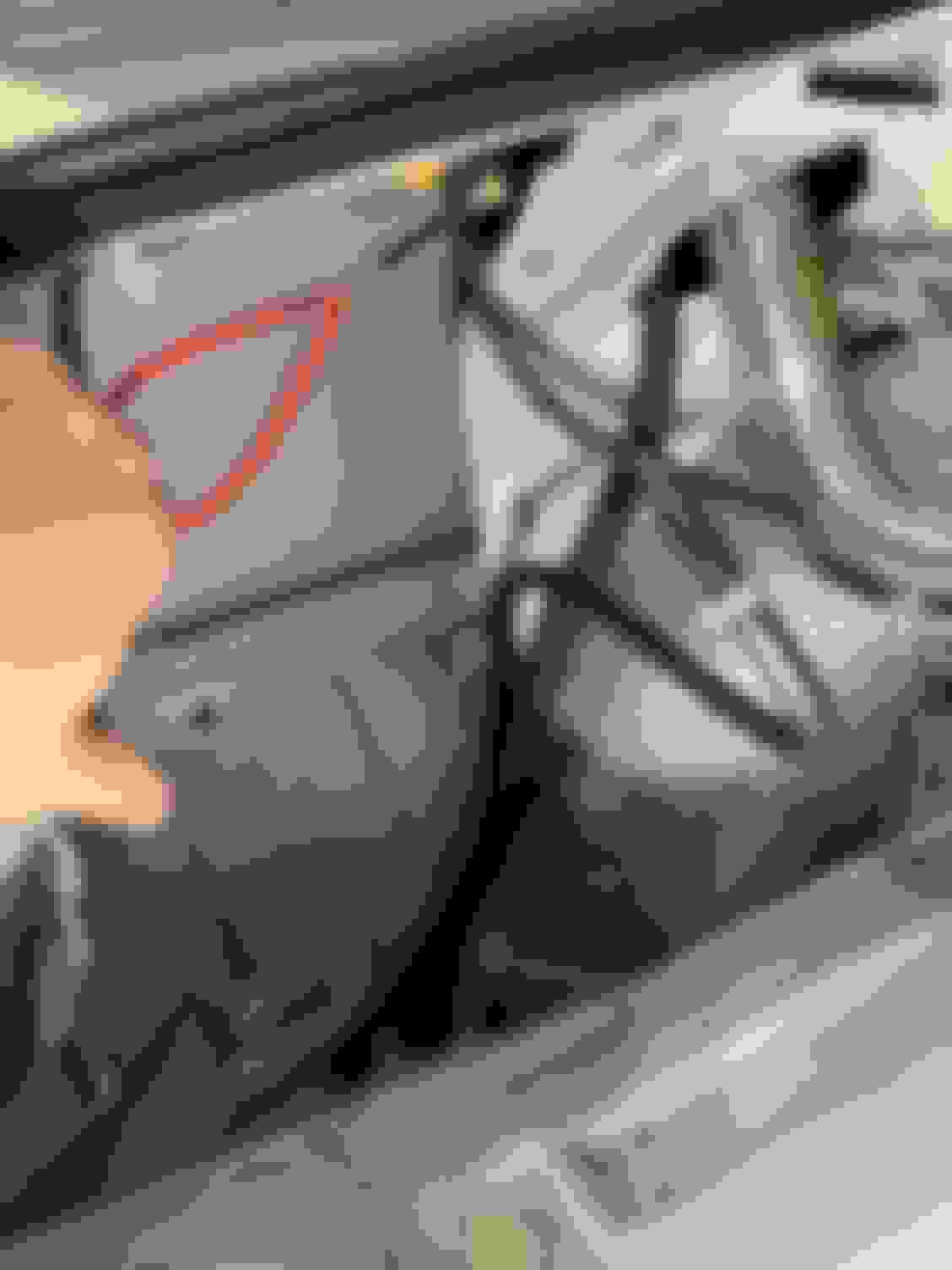
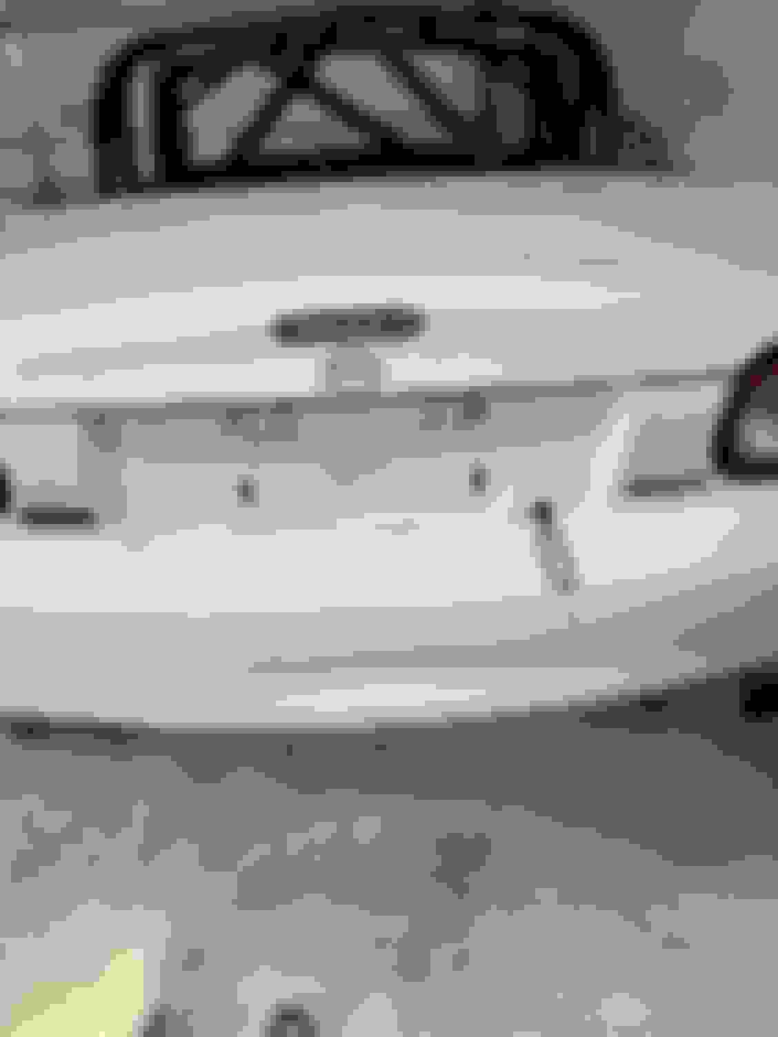
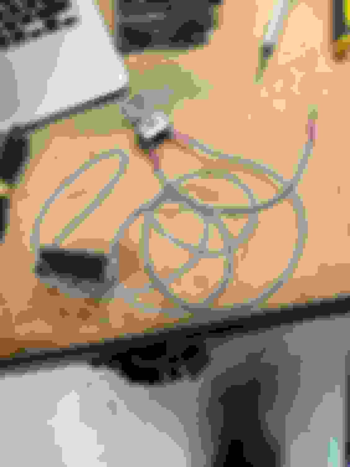
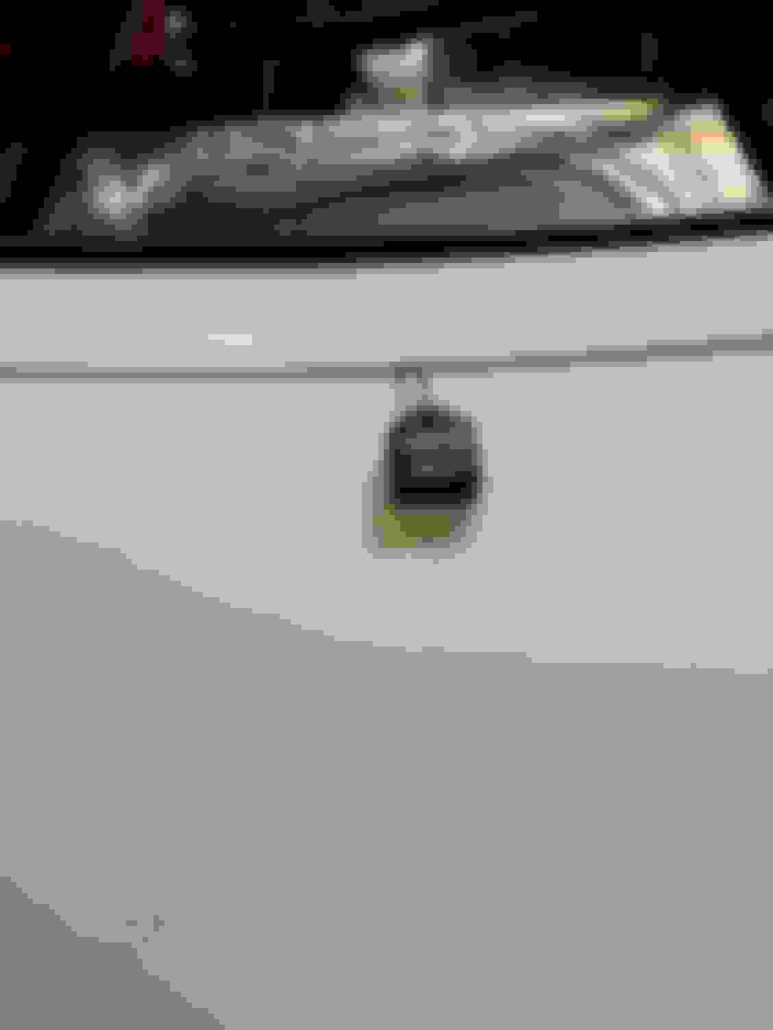
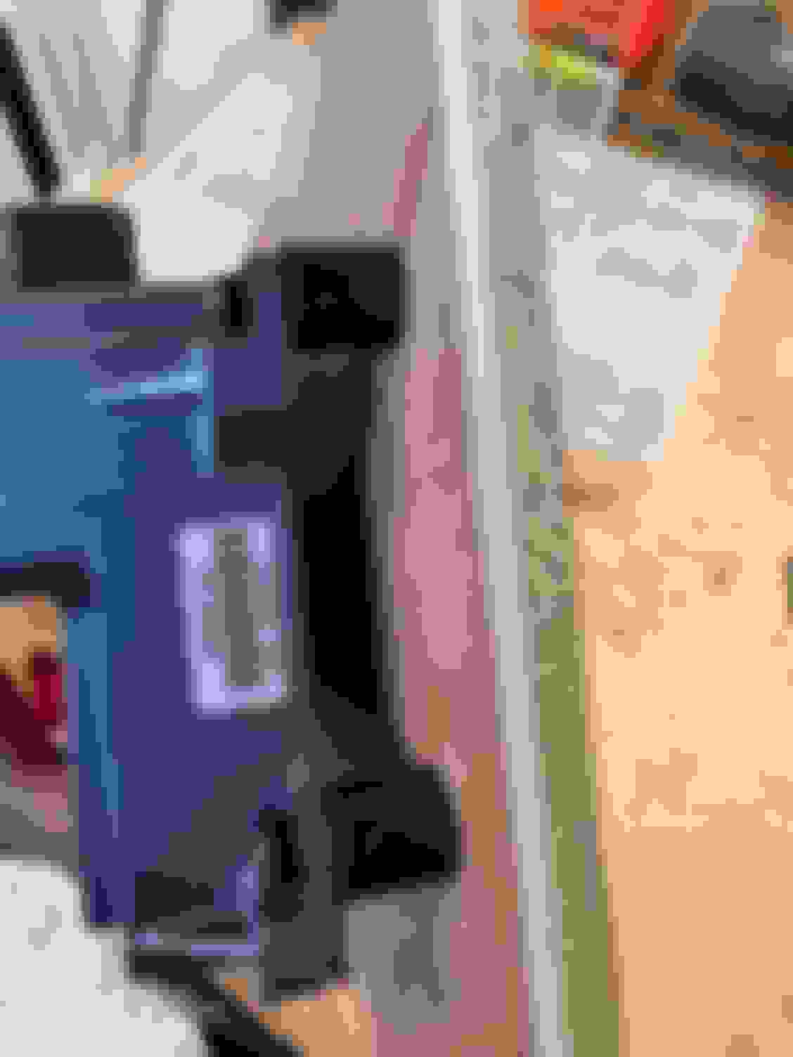
Next step was running the actual GPS. I decided to run it on the back of my trunk. You will need a way to attach the GPS unit. Somewhere I read that they recommend you use a super strength velcro, so that’s what I bought. NOTE: The trunk closes fine and doesn’t pinch the wire.
Here she is all in place
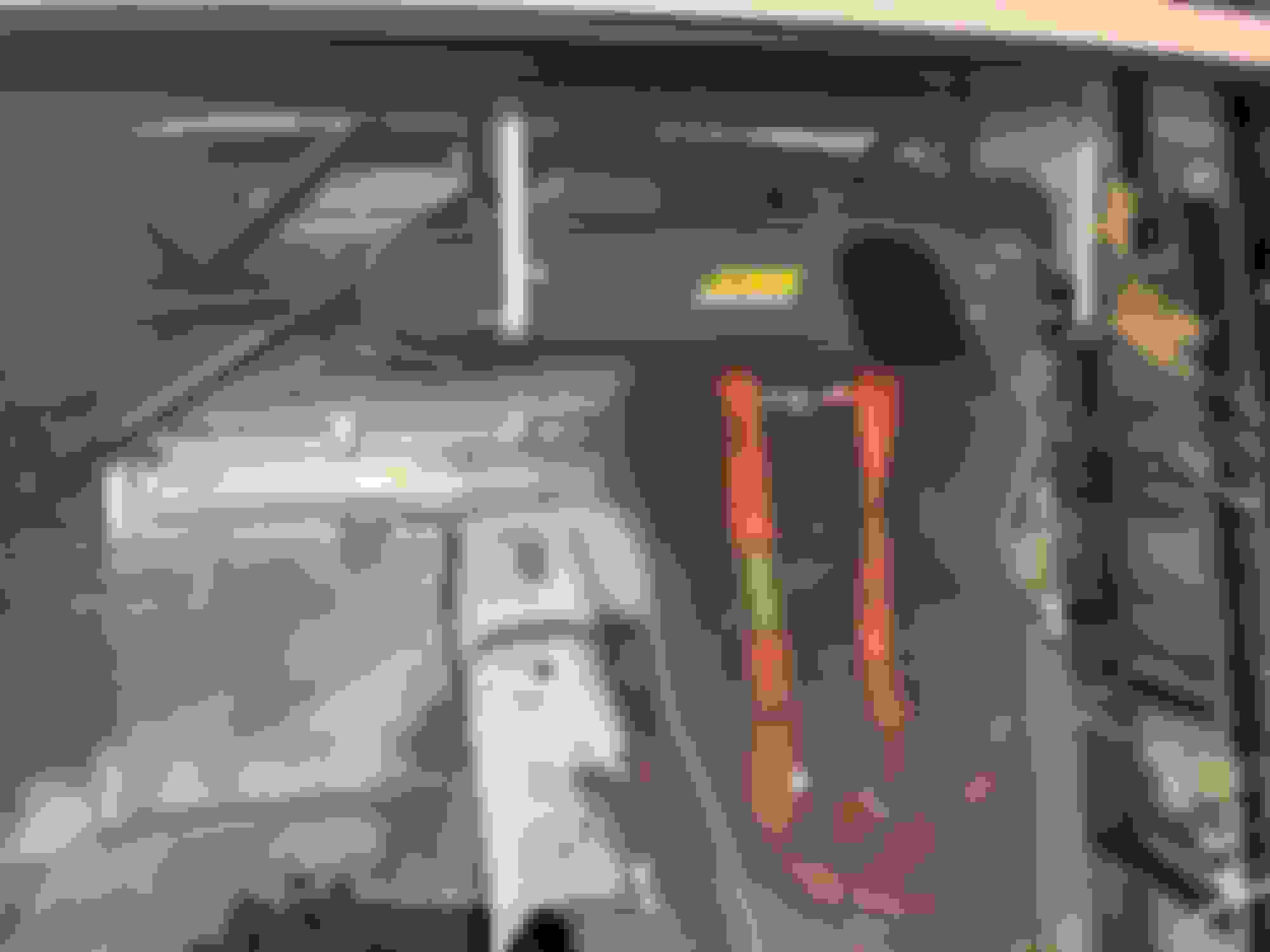
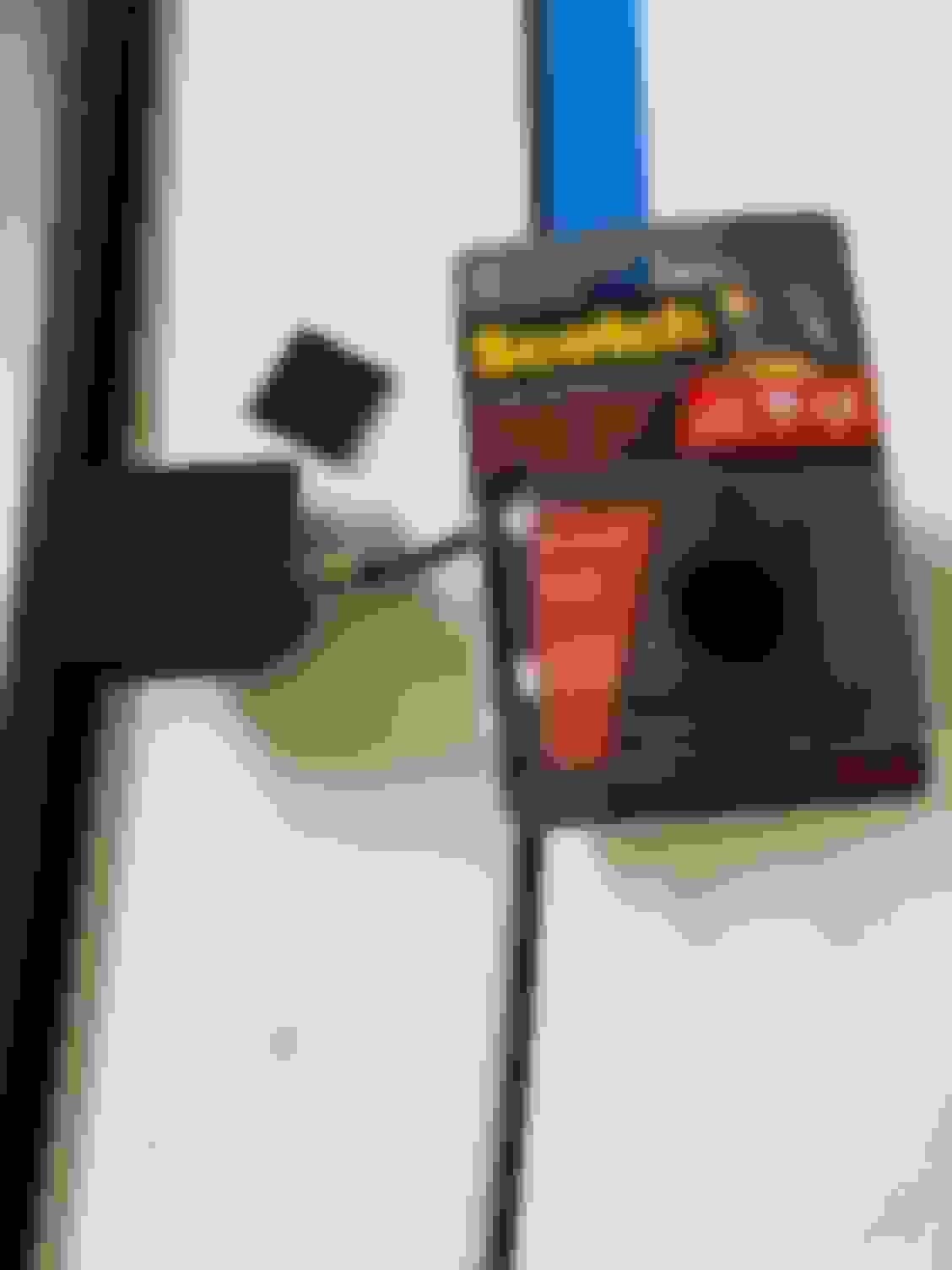
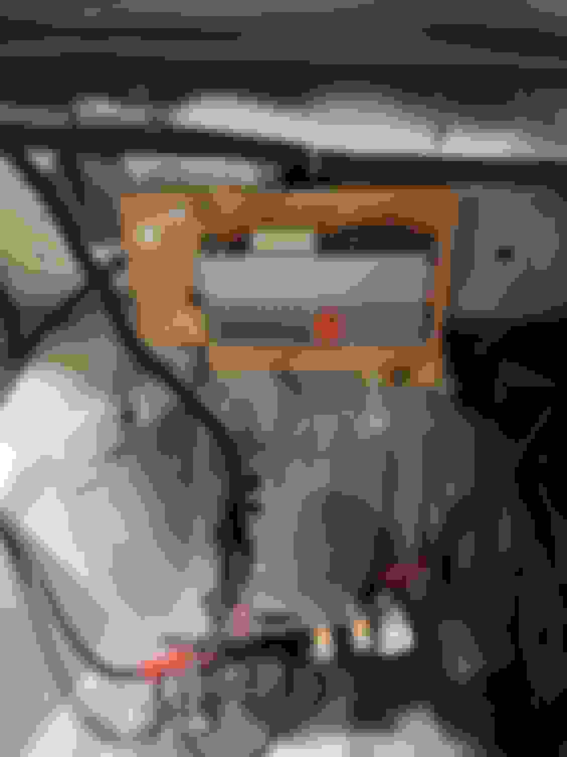
I looked at different places to install the PDM, but quickly realized that I needed to mount it where all the relays and fuses currently are, otherwise I’d have to add an extensions to all of these wires. I’m not about to do that. I still need to use this “fuse panel” for now and there is no room to mount the PDM on it, so I got creative and out of wood made a another board for the PDM and then used some threaded rod so I could mounted the “fuse panel” on top of that. It all sticks out more, so any passenger will need to be cognizant of not kicking it, but otherwise it works.
PDM on it's board
With the fuses & relays attached on top (crappy picture, but you get the idea)
I also used some rubber isolators I bought off amazon motor sports. Not sure if this was needed, but figured it wasn't a bad idea & should help keep it cooler with air being allowed to get behind the unit.
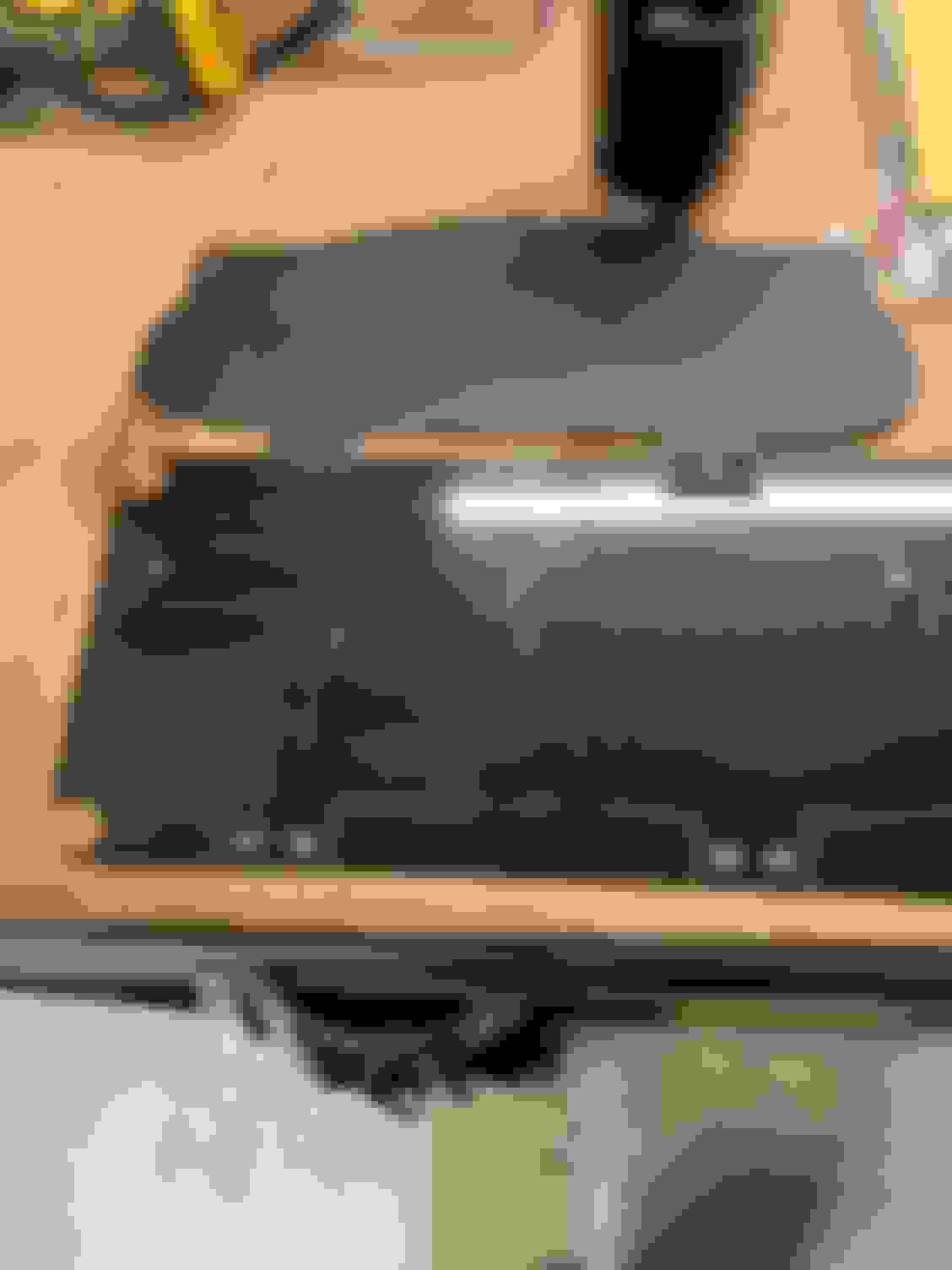
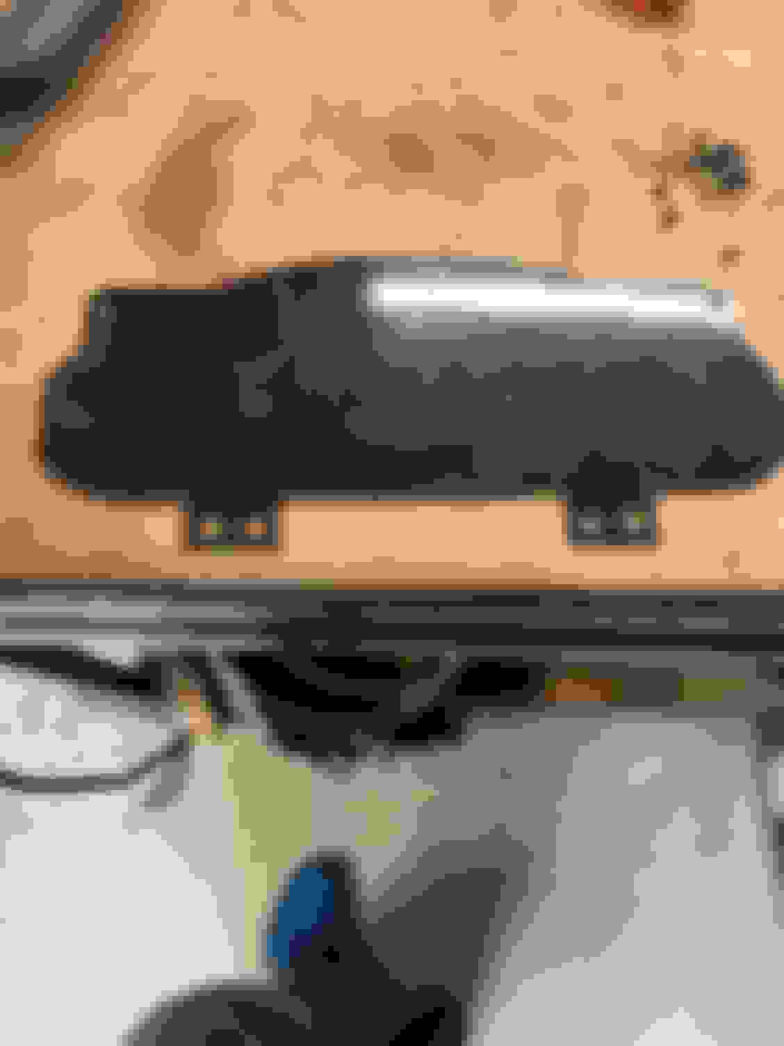
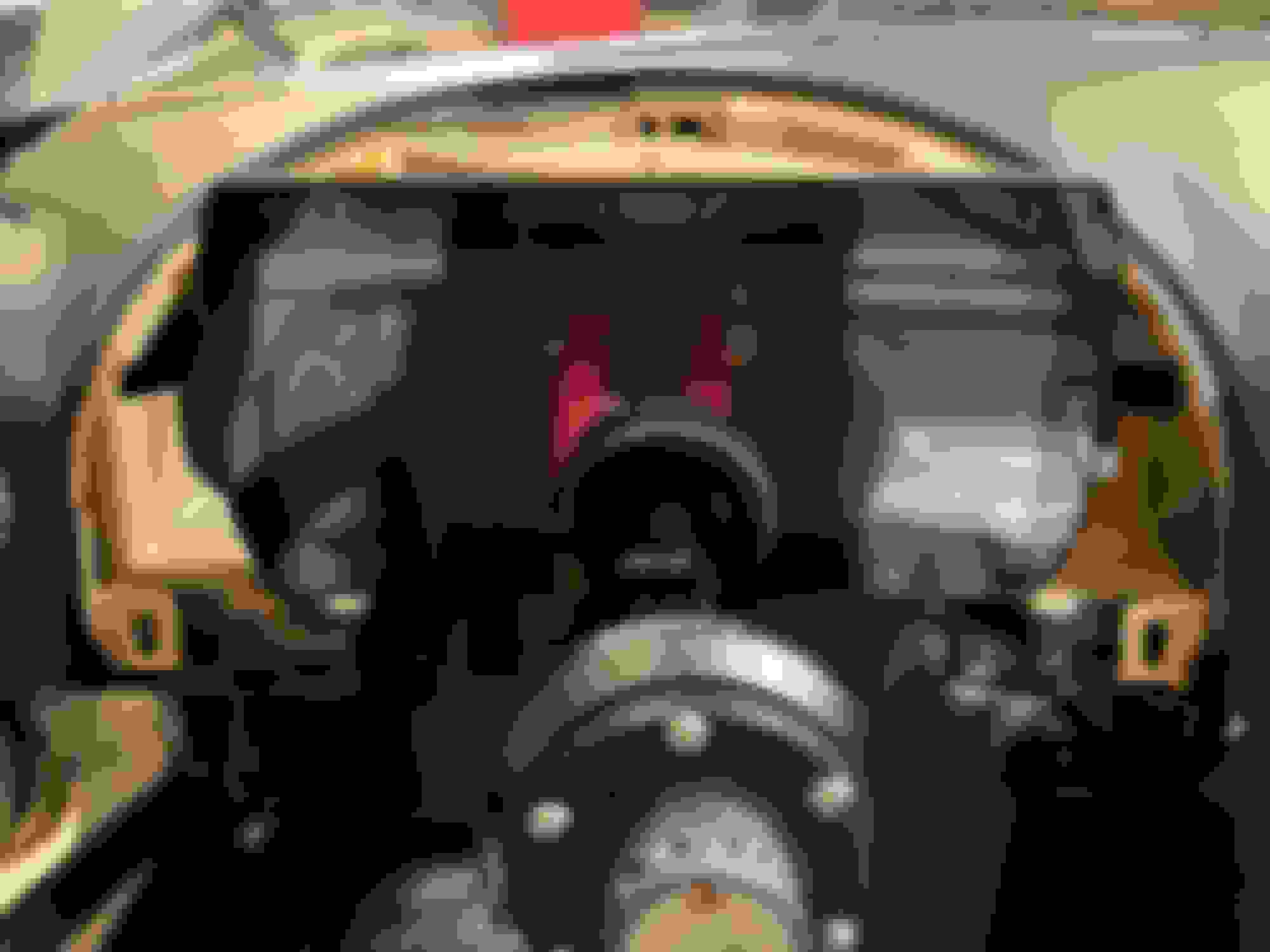
Next up was the dash. I had already made a paper template and knew the dash was a bit big, but would basically fit before buying the PDM. It covers up a few of the alert lights in the corners, but otherwise fits.
What I wasn’t expecting was how thick the screen is. It’s a bit over an inch thick. I bought a metal blank plate that’s in the shape of the dash that I could mount it too. Since I wasn’t sure if it was going to fit, I decided to mock it up with some plastic first. I had this left over piece from the Air Damn where I cut out for the radiator. I traced the metal piece onto the plastic and did some quick cutting.
Then I mocked up the holes I needed to attach the screen & screwed the screen in place. (actually had to cut out more around the connector at the top then this picture shows)
& Voila the screen was now attached to the dash.
Now for the fun part, test fitting the hood. I had to do some cutting on the hood to get it to fit. Basically, I just had to cut the bottom section to get it to fit. In the picture below you can see where I drilled holes for the corners. I cut to the holes and then across. (the silver lines are where I needed to cut across) Of course I never took a picture of this once I was done cutting & sanding it, but you get the idea in the two pictures below)
This allows the hood to snap into place, although it’s a bit tight. For now, I left it like this, but eventually, I’ll go back and cut the holes for the metal plate, I should gain back the little room I need here. FYI, the plastic does work fine, it’s a bit flexible, but once everything is in place it’s solid enough.
Lastly, I wired up the ECU to the PDM via the ECU Can bus and a couple ground wires. From there it was just a little configuration using AIM RaceStudio and upload the changes into the PDM via a USB cord. (I wish it would do downloads and uploads wirelessly, but I keep the USB cord hooked up in the car and it's easy to plug into the laptop.
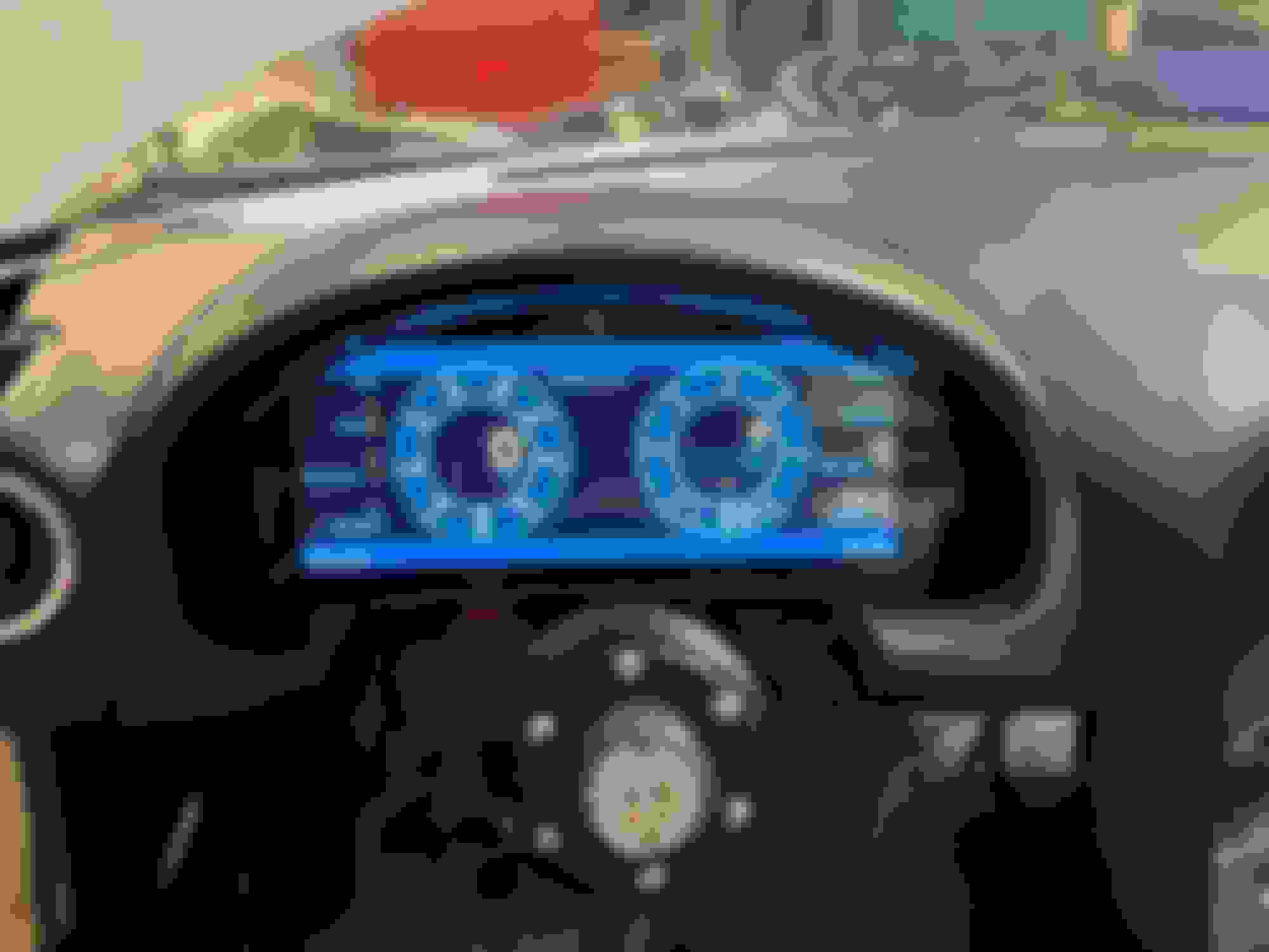
I now have gauges I can look at with my sunglasses on & a lap timer! WIN WIN.
A few notes after using this for the first time.
1. You can configure the dash to have shift lights. I thought these were going to be gimmicky and I would be changing them to predictive lap timer lights before long, but after using them…I’m a big fan. Beyond just knowing when you should shift peripherally without having to actually look at the RPM gauge, I also tried pushing myself faster around a high speed sweeper, by using them to know if “add an extra light” / see how much faster I could take a corner.
2. There is a clock. Sounds stupid, but I really like this feature too. You know how much longer you have before the end of your session, or just how much longer your going to bake in the car before your session starts. Another item I didn’t realized I “needed” but now that I have it…
3. My gauge hood is in the way on the top right & left corners more then I first realized, I’m going to need to cut back a bit more of the underside of the gauge hood so I can see them better.
4. The system does boot up pretty quickly and seems to just “work” <- I’m a huge fan of things that just work.
5. So far it looks like you must download everything to see a list of your laps and times etc. Maybe it has a way to show this on the screen, but I haven’t seen it yet. I was hoping to get a quick rundown after the session like the SOLO’s do.
Good writeup, yeah AiM sucks in may respects, as I found out with the Solo2DL - I caution people to look around, and be sure that AiM is the product for them before parting with their hard-earned. The Bookface has an Aim group, they couldn't help me but others find it useful. My observation is that if it works, you are on your (perhaps clunky) way. If it doesn't, you may be facing a world of pain coming your way, in my case the dealer was useless and it was only when I went over his head to Italy that things started happening - but even they needed convincing. The closed system is good for profits, not so good for the user.
Before I get into how I set mine all up, some items I wish I knew up front. (Most of this is a complaint) Since there is very little info / reviews on these kits.
1. Instructions are beyond lacking. The manual is 63 pages short and what little that is written isn't written very well.
2. The AMP connectors AIM choose for the PDM take a wire size of 20 - 16 gauge. The issue here is the PDM has channels that handle both 20 & 35 amps continuous. AIMs solution is to have you run two 16 gauge wires to handle all of that power. Needless to say, I'm not impressed with this "solution".
3. On the subject of the AMP connectors, a normal hand crimper isn't going to work. (I tried) You're gonna need to buy a fancy $300 crimper for those connectors. AIM makes certain of this because they use 22 or 24 gauge wire for their CAN bus that the GPS, Smartycam, Keypad, etc. use. The $300 crimper does crimp the tiny gauge wire and it holds, but it's an ugly crimp. I couldn’t get a generic hand crimper (same one I used for every single crimp on all of the other wiring on the car) to work.
4. You're going to have to wire up an on / off switch even if your using the AIM CAN Keypad (I was hoping to just use a single keypad for everything.) The keypad only works if the AIM PDM is already on.
5. The 10" screen only has 6 layouts to chose from. You can only use these layouts, but you can change what items you want to show on the layout. (i.e. Oil Pressure, Volts, Coolant Temp, etc. can be placed in any of the 6 or 8 spots, but you can’t move the spot or add additional spots)
6. The screen is thick like over an inch and she's got some weight to back up that thickness. More like it’s from the 90’s vs today. On the positive side, it seems super sturdy / you could probably run it over and it would still work.
7. You're going to need to buy more AIM “parts”. This is really just a starter kit. For example, you need to buy either a CAN Keypad for your switches, or another device (Rio02) that allows you to wire up your switches. Want to add a sensor? You need to buy a CAN Data Hub to connect it.
8. You need a windows laptop or an older Mac laptop with an intel chip that you can install windows on to run the AIM software.
9. The RaceStudio Software has an AWFUL interface. Something I would expect from the late 90’s designed and build by developers, but they skipped the UX designer. The Software seems to work well, but it’s not easy to intuitively use it. (It is pretty powerful the more I learn to use it, the I realize it allows you to do. BUT you're going to have to watch a ton of youtube videos to learn how to use it.
10. My ECU does transmit data on the CAN bus to the PDM, but all of the inputs for things that I want to use the PDM for as fuses / relays don’t come across the CAN, so you still have to wire up all those inputs. I was hoping to not need to wire up that side, and capture from the CAN message when to start the fuel pump, or turn on the coolant fan. Not a huge deal, and you could find work arounds to code this without using the ECU if you really wanted too, but that doesn’t simplify the wiring as much as I was hoping for. FYI...Your ECU may send these messages across, but I know the Chevy one doesn’t.
I also wired up the on/off switch for the PDM. I was able to hand crimp the 20 gauge wire, but I will admit, it was ugly. I may wire this up to the kill switch using it as the on off in the future, but for now I can switch it on and off separately
Then I wired up the AIM CAN connection for the GPS. This is where I hit my first snafu. For the life of me, I couldn’t crimp on the CAN wires for the GPS. The wires they used are definitely smaller then 20 gauge. The “big” wire is TXL 20 gauge wire. The small wire is the CAN wire that AIM supplies.
5. So far it looks like you must download everything to see a list of your laps and times etc. Maybe it has a way to show this on the screen, but I haven’t seen it yet. I was hoping to get a quick rundown after the session like the SOLO’s do.
My $.02, after installing a half dozen or so of these.
1....yeah
2. Keep in mind this is a motorsports capable unit, so AiM rightly assumes you'll be using motorsports level wiring components. That being said, 16 gauge tefzel wire from prowireusa (https://www.prowireusa.com/c-64-16-awg.html) crimps easily, and each 16 gauge strand can take up to 12 amps. Crimp two of them together with a 12 gauge wire into the other end of the crimp, and they can handle 20amps. I have no issues running nearly 40 through the half bridge outputs for mk60 ABS units.
3. You absolutely can use hand crimpers, I use Toolaid 18700, and use specifically the blue crimpers for all my PDM crimps. All have been tug then track tested without issue. (thanks for jinxing me)
4. Use a key on power source for the "ignition" pin of PDM. If you still have a key, use that, if not, just a 12v source from the kill switch works. I use Cartek's solid state kill switch, and wire the PDM's ignition pin to the B+ terminal.
7. You can still use all of your standard sensors, you just need to wire them to any of the 12 available channels. 1-8 are analoug and can be used for oil pressure, fuel pressure, etc. They can all be digital inputs, but 9-12 can only be digital, or on/off inputs, such as blinker switches, brake pedal switches, FP relay requests, etc. For the easy but expensive button, yes, you need a can expansion hub to thread into the can expansion cable, then a channel expander to plug into that, and your GPS (and smarty cam) plug into the CAN expander.
9. You'll get used to it. Aim's UI is notoriously bad, but once you've used it for 8 years like I have, it's like riding a bike.
10. I've never seen inputs transmitted over CAN. Most CAN protocols assume you're using it for datalogging/emissions purposes, not powering a PDM, so that information would be irrelevant to 99% of users. I'm almost always wiring an ignition relay request, FP relay request, brake switch, and oil/fuel pressure gauge if it's not an aftermarket ECU (most OE ecus never have OP/FP)
For the GPS, it is ridiculously small. Here's my solution: twist the tiny 24awg wire with a ~3" section of scrap 20-16awg wire. Do this for all 5 wires. Put that into the PDM plug, put a small piece of heat shrink on the ends of all the 3" scraps, when hot, crimp them shut with some pliers. Then slide a larger piece of heat shrink over the all 10 pieces of wire, just covering the ends of the scrap, and the final result is it'll look clean, work great, and easily slide into the connector.
For the lap times, keep in mind you can change how long the lap time is displayed for, so you can leave it up for a bit longer (or I usually shorten it to ~5-10 seconds), so you can look at your laps throughout the session. Again, AiM is assuming a motorsports vehicle, so you should be downloading data and video and analyzing it with your chassis engineer, driver coach, and/or car chief within 5 minutes of exiting the vehicle. The Solo is meant for track day stuff, you've jumped into the deep end of higher end equipment, enjoy it
Good writeup, yeah AiM sucks in may respects, as I found out with the Solo2DL - I caution people to look around, and be sure that AiM is the product for them before parting with their hard-earned. The Bookface has an Aim group, they couldn't help me but others find it useful. My observation is that if it works, you are on your (perhaps clunky) way. If it doesn't, you may be facing a world of pain coming your way, in my case the dealer was useless and it was only when I went over his head to Italy that things started happening - but even they needed convincing. The closed system is good for profits, not so good for the user.
Will follow your progress with interest.
I remember reading your struggles with AIM. It played into my decision process, but at the end of the day, I choose the AIM unit. At my price point / what I was looking for, there really are only a small group of players. AIM, Racepac, and AEM. I felt AIM was the best for my needs.
I may have complained a bit more in my write up then I should. All in all, it works and I'm pleased. AIM is a small company and I'm glad someone offers these products to us, even if there are some parts I would do differently.
My $.02, after installing a half dozen or so of these.
1....yeah
2. Keep in mind this is a motorsports capable unit, so AiM rightly assumes you'll be using motorsports level wiring components. That being said, 16 gauge tefzel wire from prowireusa (https://www.prowireusa.com/c-64-16-awg.html) crimps easily, and each 16 gauge strand can take up to 12 amps. Crimp two of them together with a 12 gauge wire into the other end of the crimp, and they can handle 20amps. I have no issues running nearly 40 through the half bridge outputs for mk60 ABS units.
3. You absolutely can use hand crimpers, I use Toolaid 18700, and use specifically the blue crimpers for all my PDM crimps. All have been tug then track tested without issue. (thanks for jinxing me)
4. Use a key on power source for the "ignition" pin of PDM. If you still have a key, use that, if not, just a 12v source from the kill switch works. I use Cartek's solid state kill switch, and wire the PDM's ignition pin to the B+ terminal.
7. You can still use all of your standard sensors, you just need to wire them to any of the 12 available channels. 1-8 are analoug and can be used for oil pressure, fuel pressure, etc. They can all be digital inputs, but 9-12 can only be digital, or on/off inputs, such as blinker switches, brake pedal switches, FP relay requests, etc. For the easy but expensive button, yes, you need a can expansion hub to thread into the can expansion cable, then a channel expander to plug into that, and your GPS (and smarty cam) plug into the CAN expander.
9. You'll get used to it. Aim's UI is notoriously bad, but once you've used it for 8 years like I have, it's like riding a bike.
10. I've never seen inputs transmitted over CAN. Most CAN protocols assume you're using it for datalogging/emissions purposes, not powering a PDM, so that information would be irrelevant to 99% of users. I'm almost always wiring an ignition relay request, FP relay request, brake switch, and oil/fuel pressure gauge if it's not an aftermarket ECU (most OE ecus never have OP/FP)
For the GPS, it is ridiculously small. Here's my solution: twist the tiny 24awg wire with a ~3" section of scrap 20-16awg wire. Do this for all 5 wires. Put that into the PDM plug, put a small piece of heat shrink on the ends of all the 3" scraps, when hot, crimp them shut with some pliers. Then slide a larger piece of heat shrink over the all 10 pieces of wire, just covering the ends of the scrap, and the final result is it'll look clean, work great, and easily slide into the connector.
For the lap times, keep in mind you can change how long the lap time is displayed for, so you can leave it up for a bit longer (or I usually shorten it to ~5-10 seconds), so you can look at your laps throughout the session. Again, AiM is assuming a motorsports vehicle, so you should be downloading data and video and analyzing it with your chassis engineer, driver coach, and/or car chief within 5 minutes of exiting the vehicle. The Solo is meant for track day stuff, you've jumped into the deep end of higher end equipment, enjoy it
I’m still not crazy about needing to run two smaller wires to 2 separate pins to get the required amps needed for the bigger circuits, but it is what it is. Happy to hear it works with your MK60 ABS, I’m gathering parts right now for an MK60e5 and it will probably be the very first “electrical” item on the PDM.
With your trick on getting the 24awg wires (which I really like! for you!) to crimp, I could probably use the hand crimpers for everything. The crimps would probably look ugly, and my guess is I would toss a few more pins along the way due to bad crimps that had to be redone, but I think I could make a generic crimper work in that instance. BTW, I always saw people folding the wire back on itself and crimping to get a smaller wire to work, but never been a fan. Your way, of adding extra wire & heat shrinking it etc. is a great idea. Thank you!
I’m a bit concerned about running out of input channels, but I really haven’t taken the time to count out how many I need etc. The keypad (still need to purchase) should cover the switches, and besides already using one for the fuel gauge, I have all the others left. I’m probably concerned about nothing.
I’m fairly new to car wiring & can bus, I naively thought most ECUs sent an input signal on the can bus too, but totally makes sense why it doesn’t after what you said / thinking about it.
I’ve only used the PDM for 3 track days now & the first one was trying to figure out how to download my data / why it wasn’t recording the laps at first. I have it now showing me my lap time like you suggested. I just need to learn race studio better and get my lazy driver / chassis engineer / driver coach / car chief into the habit of downloading the data after each session and looking at it vs sitting down in the nearest lawn chair and complaining about his motion sickness
As always, Thanks for the info Curly! it’s very helpful.
Great thread and thanks for posting the AIM info! This discussion is really helpful to me as my car is getting a complete re-wire on a PDM32 at the same time as a K swap. I'm trying to soak up the info I can on the PDM and AIM stuff in general, and as you noted things are not all that well documented.
I also tried to do things cheaper (ASL/Race Capture) and the results were less than satisfactory, and integration with display/video was pretty much on the end user. AIM isn't cheap, but it's about the only 'total package' available that's within reach of us weekend warriors.
Really cool and inspirational DIY build you have going on here! Thanks for all the updates!
Thanks Fireindc, I really appreciate you saying that. It's been a HUGE project and a lot more work then I expected, but also very rewarding and I really enjoy it every time I get to take her out on the track.
Originally Posted by Roda
Great thread and thanks for posting the AIM info! This discussion is really helpful to me as my car is getting a complete re-wire on a PDM32 at the same time as a K swap. I'm trying to soak up the info I can on the PDM and AIM stuff in general, and as you noted things are not all that well documented.
I also tried to do things cheaper (ASL/Race Capture) and the results were less than satisfactory, and integration with display/video was pretty much on the end user. AIM isn't cheap, but it's about the only 'total package' available that's within reach of us weekend warriors.
Thanks Roda! Feel free to ping me if you have any questions. I probably don't know the answer, but happy to help figure it out. There is a group on Facebook that seems very helpful with the PDM questions. (more of the logic coding questions, but still helpful)
You hit it on the head why I choose AIM, its a total package that isn't cobbled together like I use to do with my phone. I might not be crazy about everything, but compared to my other options, it's the best fit.
I just bought a used smartycam to add to the system. I love how it just works. Instant integration with the data & wired into the car with auto on/off. I will admit that I had a very hard time stomaching the price for even a used camera with crappy picture quality, but the integration & "just works" won the day.
I just bought a used smartycam to add to the system. I love how it just works. Instant integration with the data & wired into the car with auto on/off. I will admit that I had a very hard time stomaching the price for even a used camera with crappy picture quality, but the integration & "just works" won the day.
The camera prices are my biggest heartburn with AIM... they're just so out of line with everything else on the market. But, I've tried GoPros, knock offs, and other types of action cams and they all suck. "Just works" is worth a lot of $$$ as it turns out.
I remember reading your struggles with AIM. It played into my decision process, but at the end of the day, I choose the AIM unit.
Glad you are happy with the AiM, I don't/didn't want to turn people off the AiM, just open eyes. My problems were probably 99% local distributor, 1% Italy. But when I turned Italy around, they moved fast to fix the problem - like a couple of weeks after I sent them an email setting out the problem, they had bench tested the Solo with the Autronic, found that, yes there was problem, and implemented a solution. Can't complain about that, pity it took three years to get there though. /thread drift
Since we are on the subject of the AIM PDM32, I've made another change to it that I figured people might be interested in. I got the gas gauge working, albeit in a very unorthodox, blind squirrel gets a nut sort of way. My car was having fuel starvation issues coming out of long left hand sweepers. I read up that it was most likely the fuel sock having a hole in it and to replace that first. So out came the fuel pump & sensor and on went a new fuel sock.
The new sock has a couple springs inside it and stays more "open" then the old sock ever did. (Spoiler, this sock didn't fix my problem, although it did make it a little better. I went from having 8 gallons left in the tank and having fuel starvation to 6 gallons left in the tank and having the issue)
Getting a fuel gauge working on the car was a higher priority since I started driving her. I never knew if she was about to run out of gas somewhere or not. I also didn't even have an odometer / didn't really have a clue about the MPG she got on the road or on the track, so I took a lot of trips to the gas station. Since I already had the sensor out of the tank, it would be easier to test & make certain things were working properly. Since I could manually move the sensor arm.
I was told I needed an Iron Canyon Motorsports Fuel Sending unit to get things to work with the AIM dash. Unfortunately all the ICM fuel sending units were/are sold out. (I think they might be out of business.) So I went looking and found this cheap dolphin fuel ohm range converter, which was supposed to work with any fuel gauge / any sender.
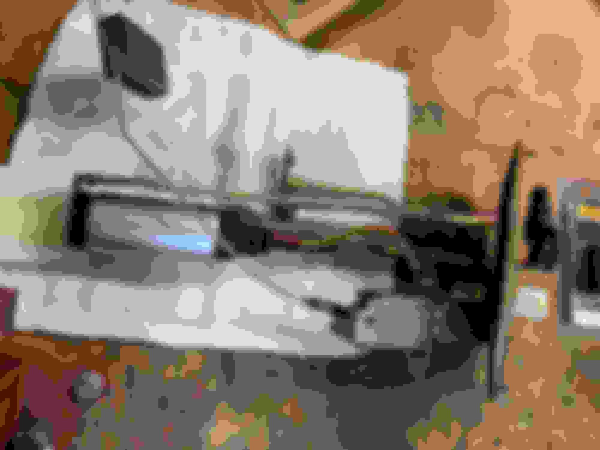
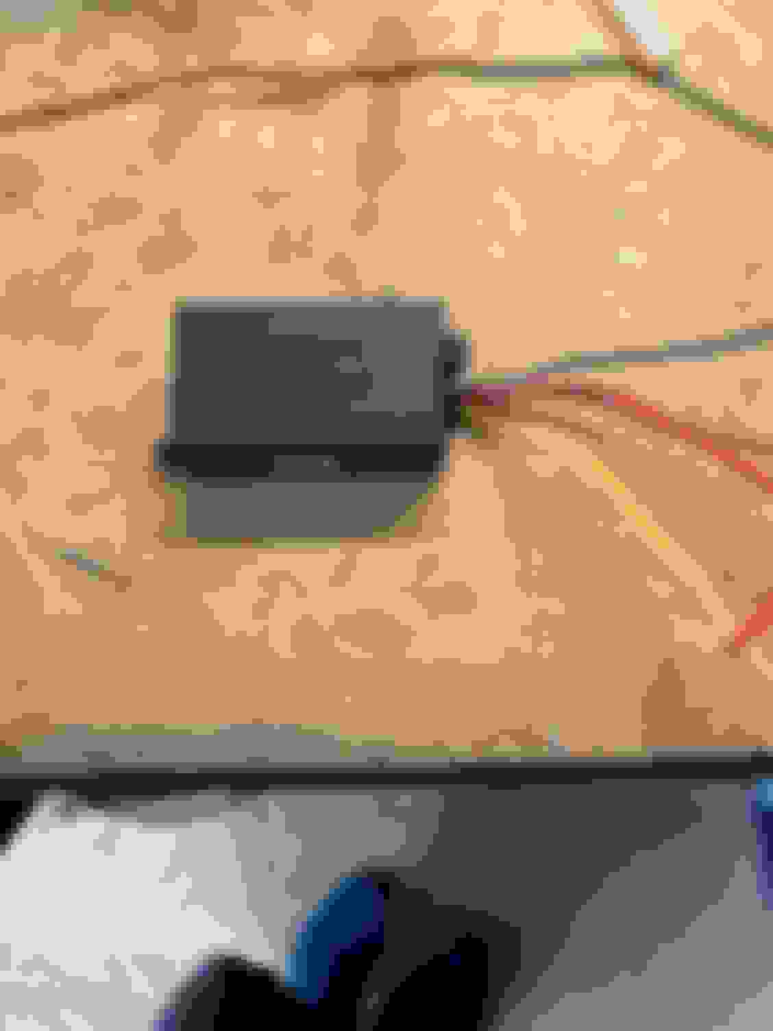
I wired up the dolphin as much as possible on the bench before adding to the PDM and fuel sender.
I had tucked the fuel sender wire up at the drivers kick panel a while back when I wired everything, wait for my gauge solution. (Stock it was split into two wires, one for the gauge the other for the ECU. I removed one of the leads since I only needed one wire.)
The Dolphin wants you to give it 3 values, Empty, Half Tank, Full, and from there it can figure out the rest. It's made to work with an analogue gauge. You move your sender all the way to full and then program what full is by turning the calibration screw till your gauge shows full.
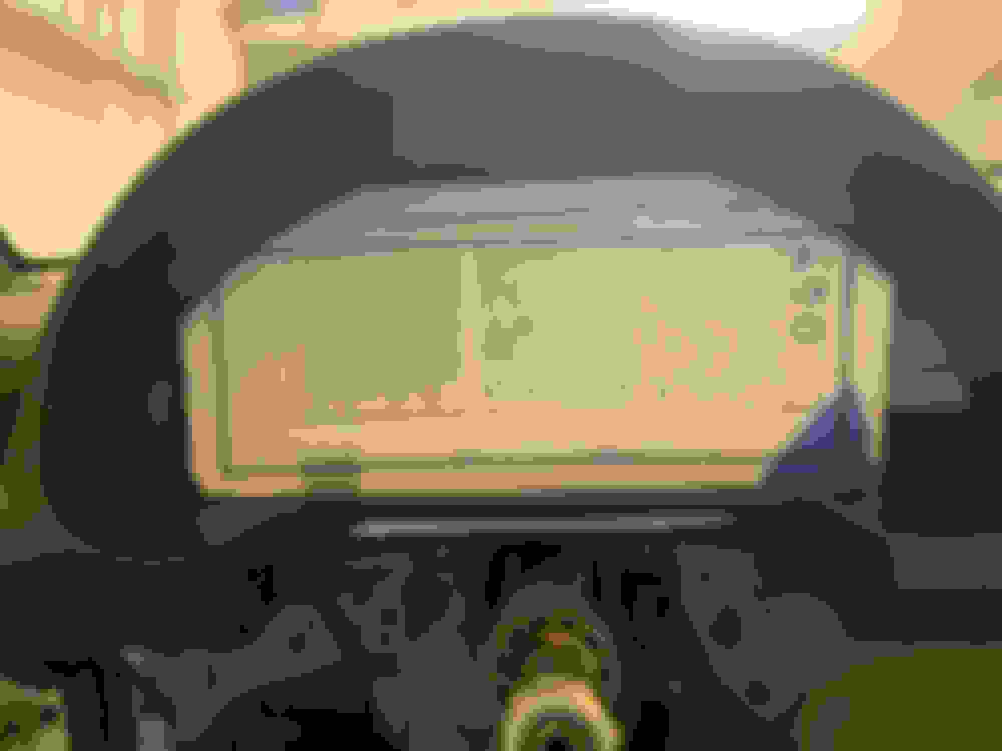
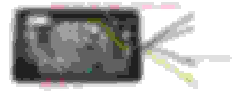
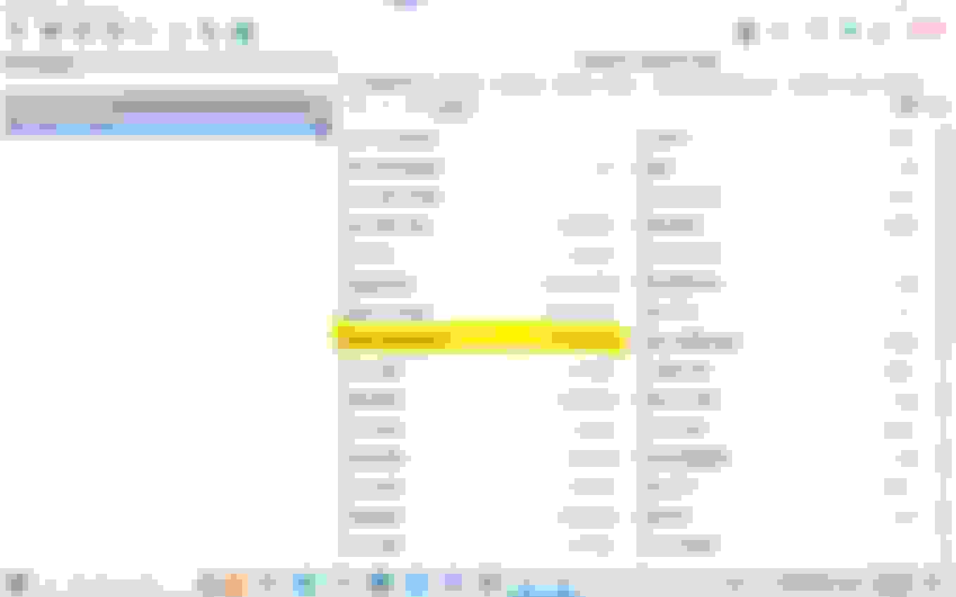
I fired up RaceStudio and hooked my laptop up to the PDM. Hidden amongst the RaceStudio functions is a page that shows you a view of all of the current inputs and values coming into the PDM. So all I had to do was move the fuel sender to Low and record that value, then half, and lastly full. I figured if the values were really close I would "calibrate" the Dolphin so that the values sent to the PDM were further apart.
I took this picture tonight. If you look at the highlighted item Ch1In1FuelSensor is showing 5.1 gal with a [97] besides it. The 97 is the mV value. When I originally did this it didn't show the gallons, it's doing that now because I have everything set up.
For the life of me, I couldn't get this to work. The values were all over the place and not consistent. I also suspected that this wasn't giving me a 0-5 volts output and then I reread everything and it said it was just adjusting the ohms and didn't mention anything about the 5 volts. The funny thing is that the PDM accepted ohms for the input or mV. I tried it both ways. In the end I pulled the Dolphin out. It either wasn't working or wasn't needed.
So before going forward, let me be very candid here...I am NOT an Electrical Engineer. I have a very rudimentary knowledge of simple circuits and honestly still don't know how what I did works, but I decided to wire up the sender directly to the PDM to see if I could get it to read directly using the ohms. I played around and ended up switching it to millivolts and used a 2K pull up resistor (that the PDM has built in) and after that I was getting a signal that was repeatable and went up or down depending upon if I moved the fuel sender from empty to full. Success!
I really didn't want to empty the tank and fill it back up one gallon at a time taking measurements, so I went looking to see if anyone else had all of the measurements. (Measurement being how many volts the sensor sent for a given amount of gas in the tank.) I knew I was measuring millivolts vs 0-5 volts, but figured since I had the full and empty numbers I could figure out the ratio different and convert everything into my measurements. I asked the PMD group on Facebook if anyone had all of the middle values and immediately got "That won't work, you need the ICM piece". I uploaded the following video showing it worked and asked if this was causing some sort of issue and never got a response. (So if you are an EE or just knowledgable about this, if I'm doing something wrong, please let me know. I would rather not break my PDM doing something stupid, but since it's only sending millivolts, I'm not very worried about breaking anything / this has been working for 8 hours of "run time" by now / almost 2 months.)
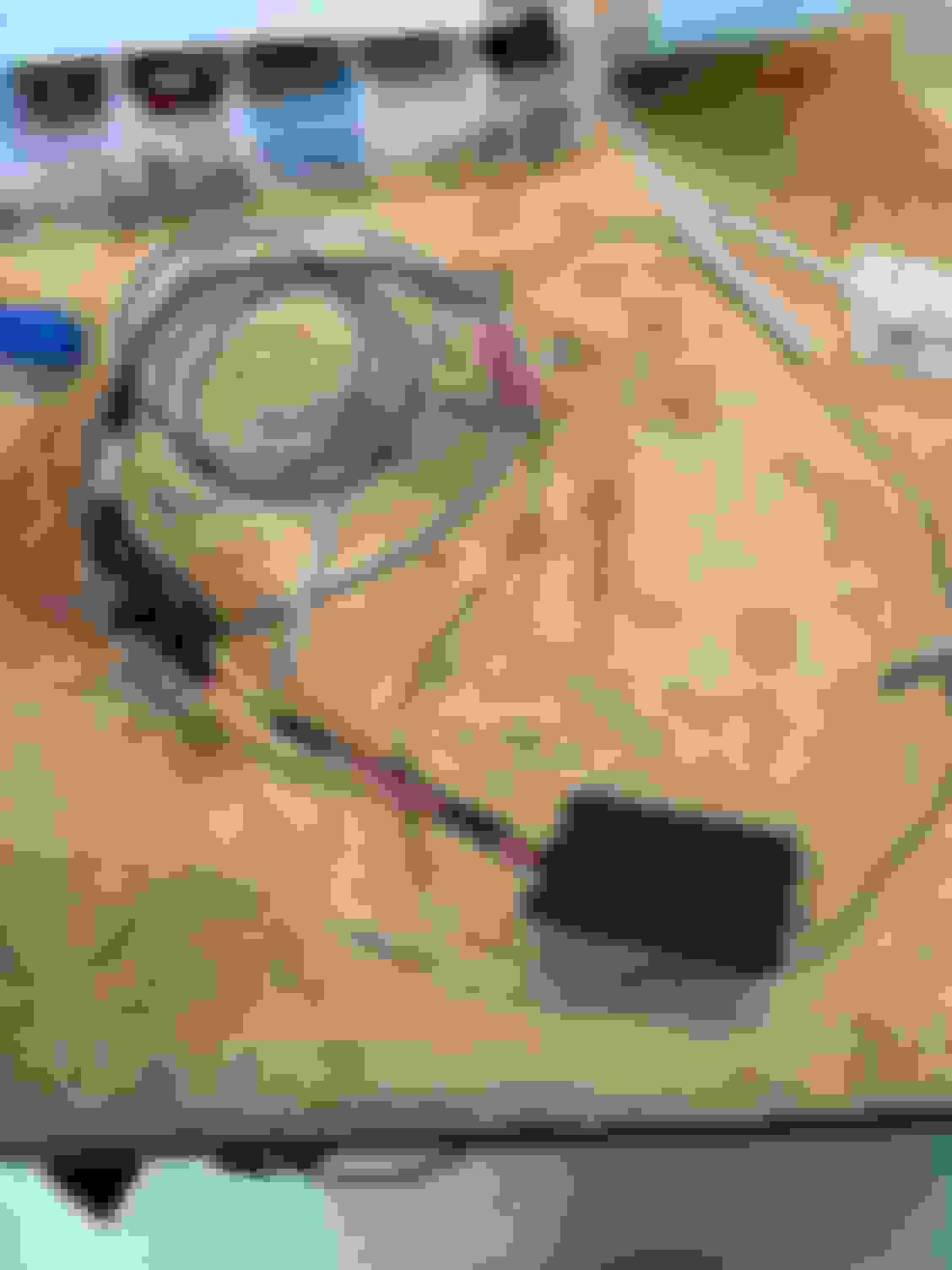
Next step was figuring out what the voltage value was for each gallon of gas. First step was getting all of the gas out of the tank without making a mess. Last time I did this the hose feel off my battery powered pump and I was wearing / had half a gallon of gas all in the car. Instead of using the battery powered pump, I decided to put the real pump back in the car and use it to empty the tank. I took a piece of hose and put it on the one end and ran that down to a gas can. From there I turned on the power to the car, but didn't start it. I thought I was being clever until the pump turned off a couple seconds after starting. Damn it, I thought it primed until the fuel pressure was a certain amount up at the fuel rail, but now I know it's basically just a timer. OK plan B, I removed the relay for the fuel pump and used a jumper to hot wire the pump. Using the master power switch to turn it on and off that way. (So I could stop the pump before it overfilled my gas can.) This worked great for emptying the tank.
Next step was figuring out exactly what 1 gallon was and how to replicate that amount each time. I brought a 2 gallon gas can to the gas station that's half a mile down the road and filled it up with exactly 1 gallon of gas. I brought this home and pulled out a scale and weighed it. From there it was just a slow slog of filling up the car, taking the measurement, and then filling up another gallon of gas and rinsing / repeating.
Once I was done recording all of the numbers, I laid them out in RaceStudio so it could calculate how many gallons of gas I had left based upon the mv measurement. Note, I filled up over a gallon of gas in the tank before any measurement changes took place from the tank sensor. I guess it doesn't go all the way to the bottom of the tank. I also filled up the tank with another gallon after it stopped reading. I sort of "smoothed" my numbers at the very top and very bottom to give me a closer reading.
I also had to configure the channel in RaceStudio. The channel has a setting in it (the low pass 16 seconds value) that slows down all the readings to handle the "sloshing" so you don't have the numbers on the screen jumping all around.
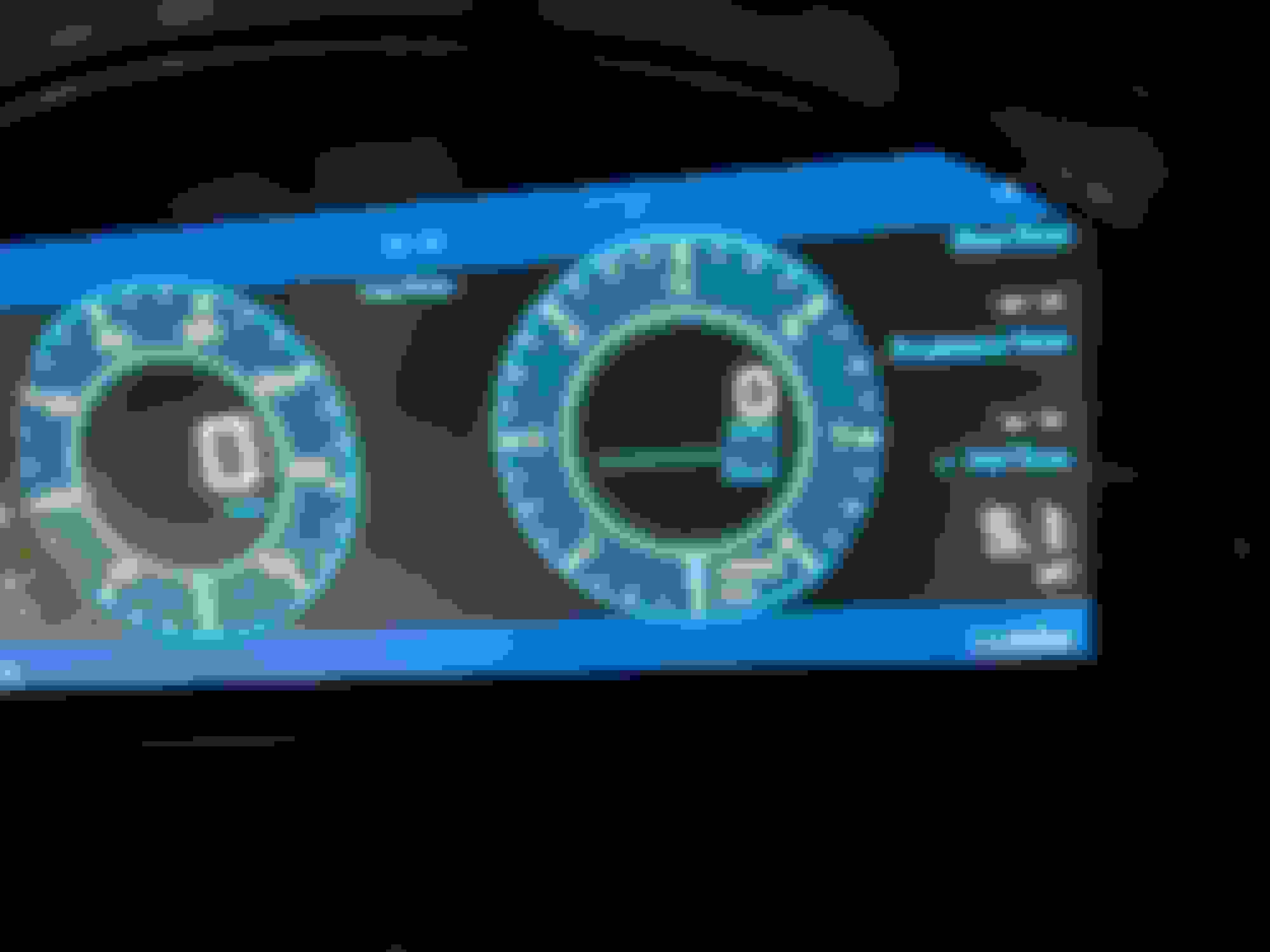
And here is the end result...I currently have 5.1 gallons of gas in the tank. (Crappy picture, but you get the idea)
 11-17-2022, 09:07 AM


 1
1