F20C Miata engine conversion
#1
Thought I'd share this with you guys. Customer wanted to swap an f20c in his miata, so I took on the project. Customer dropped off the car Friday, I've spent yesterday and today to get to where I am now, I should have it wrapped up tomorrow, Tuesday at the latest.
follow me on Instagram guys, I post all sorts of cool fab stuff there - zanderguerra
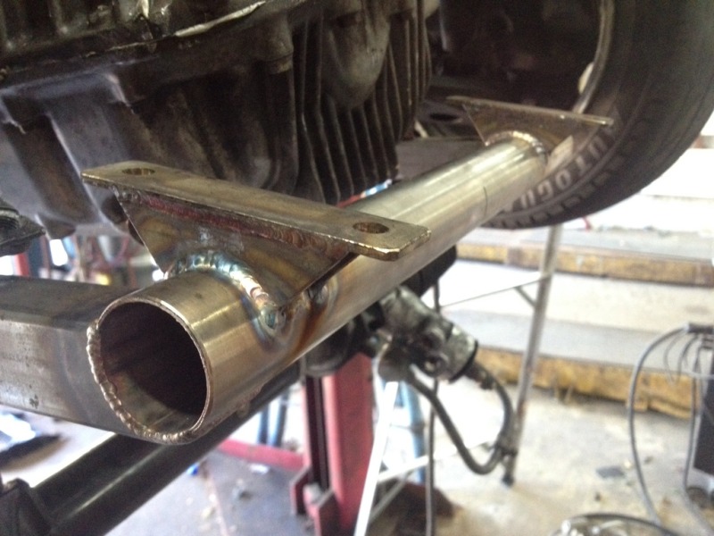
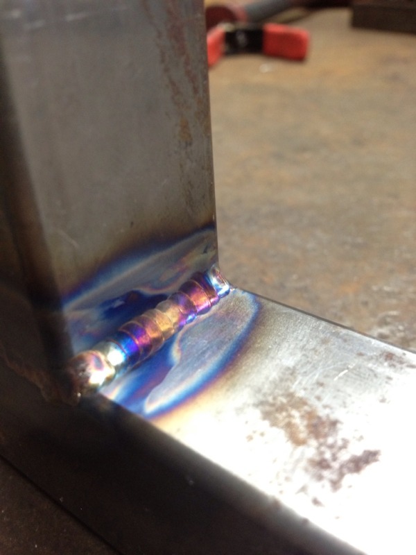
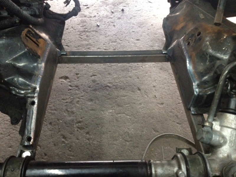
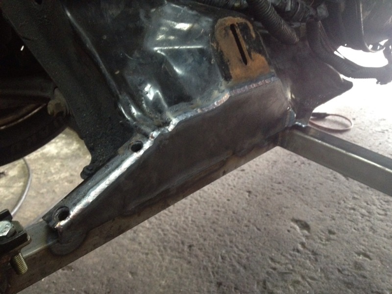
Here is the subframe addition, 1.25" square and 1.5" round, all tig welded.
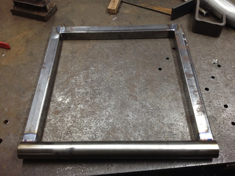
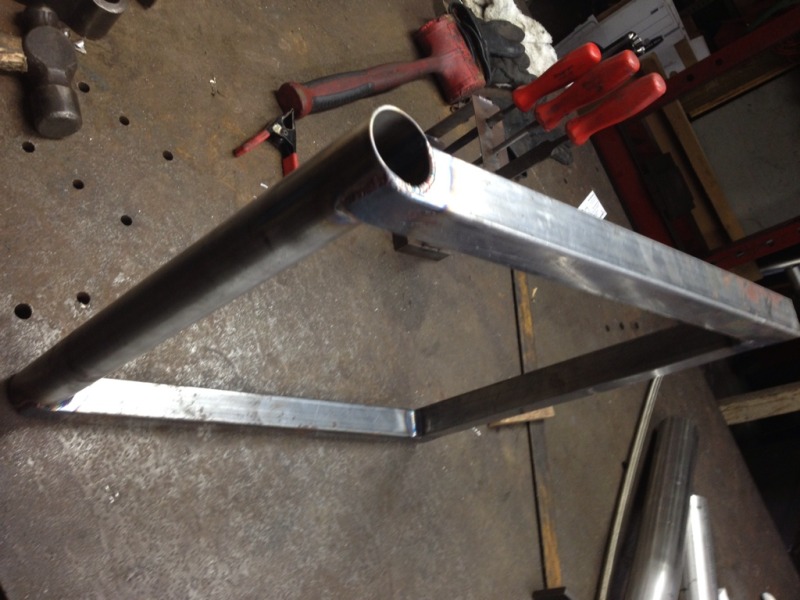
I welded it onto the bottom of the subframe
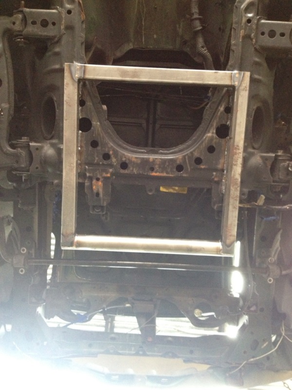
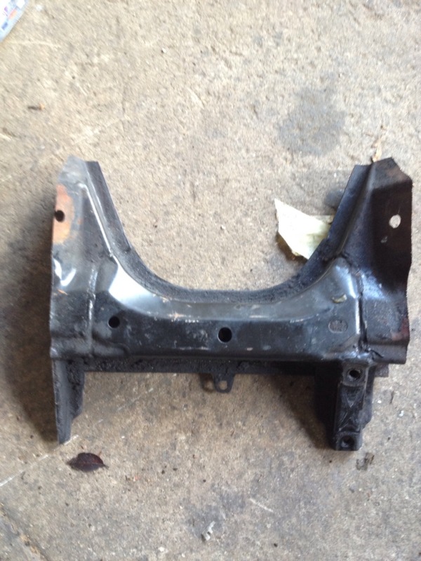
And cut what I didn't want anymore away with a sawsall
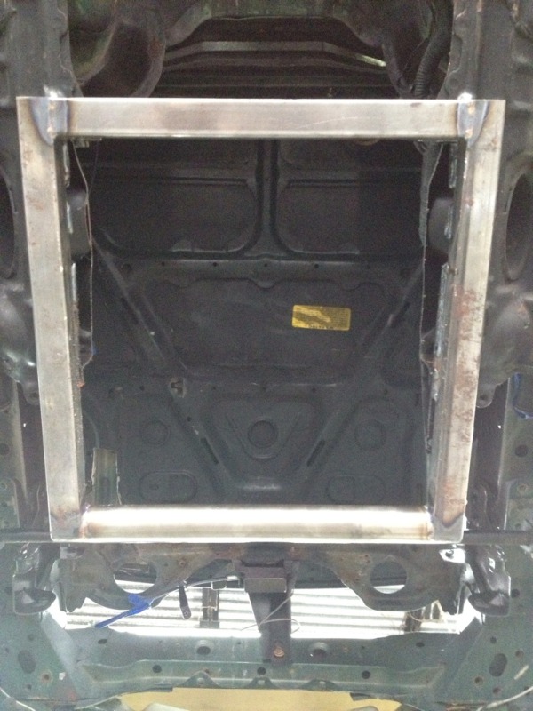
I will be boxing In all of the open areas around the stock subframe, and adding a few reinforcements before this is done.
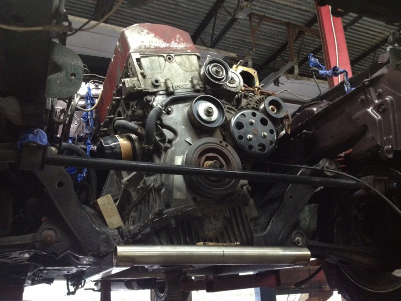
Engine shimmed and tweaked into position. Yes you loose ground clearance with this swap, the engine is too tall for the miata without being positioned farther back. I built it to sit a slight bit lower than the sump, to protect it.
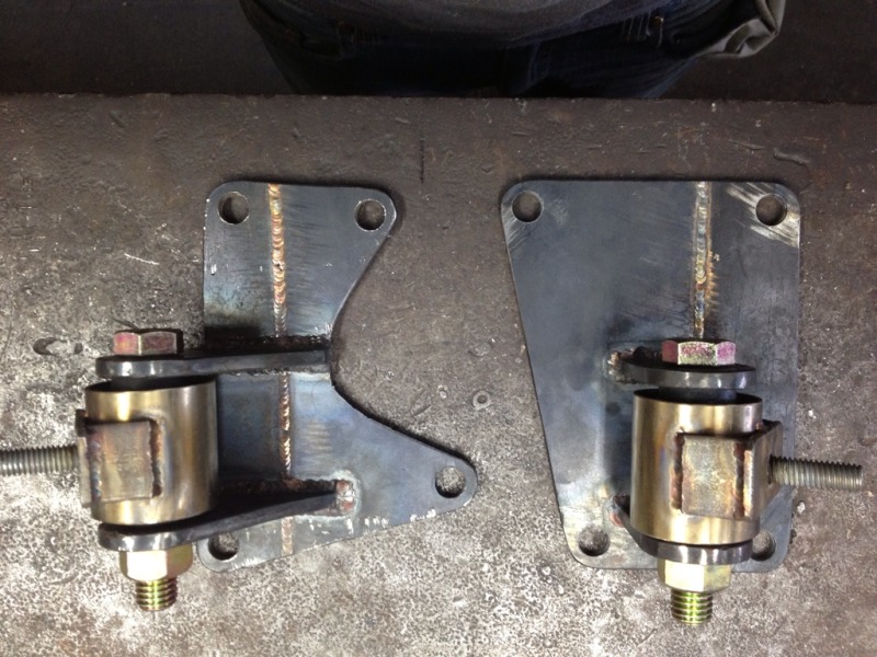
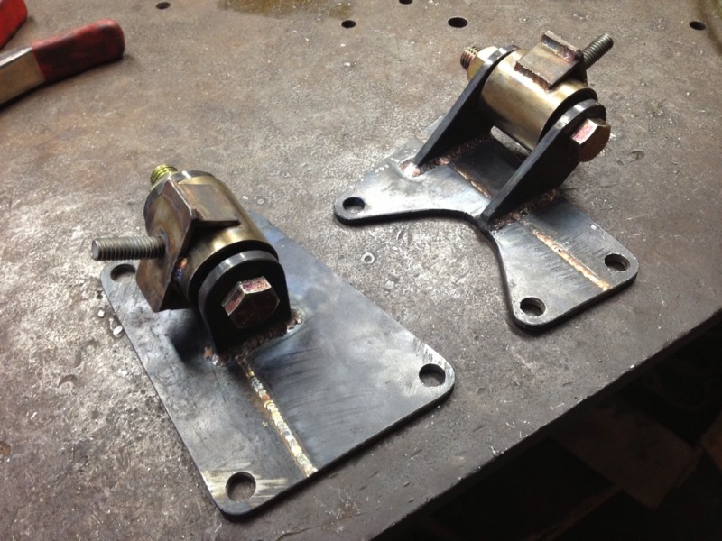
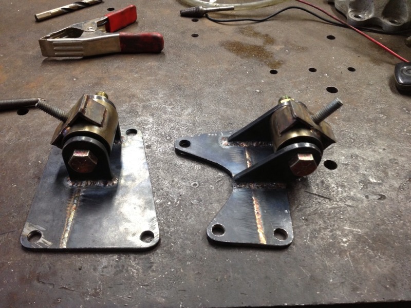
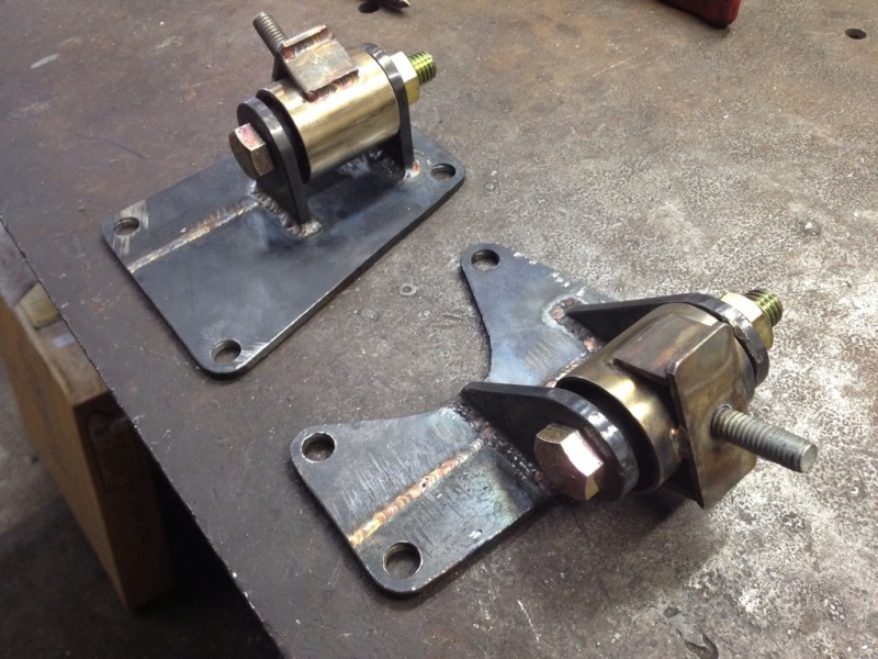
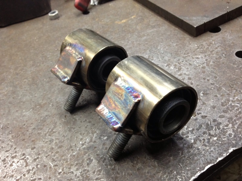
Close up of the subframe side of the mounts
Don't mind the bolts not being in all the way, or there being a piece of stainless stock through the mount hole, it's all just mocked up in these photos.
Driver side
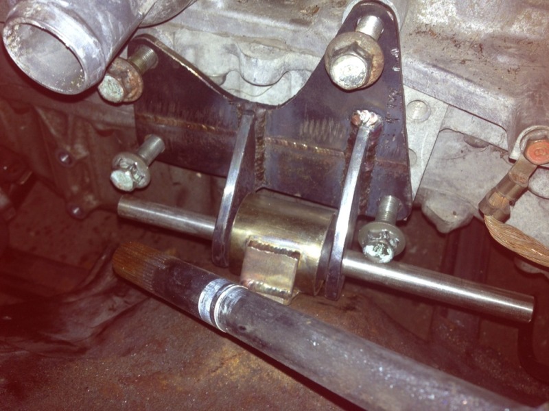
Passenger side
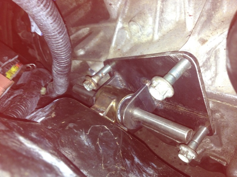
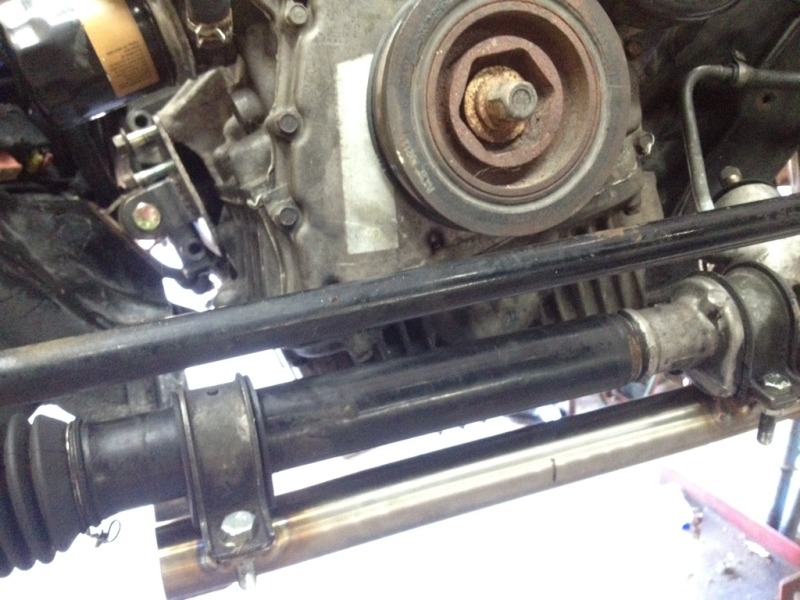
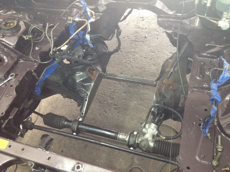
I have the steering rack mounts made and sitting in this picture, but it's not aligned or welded yet, I was tired and didn't feel like working anymore
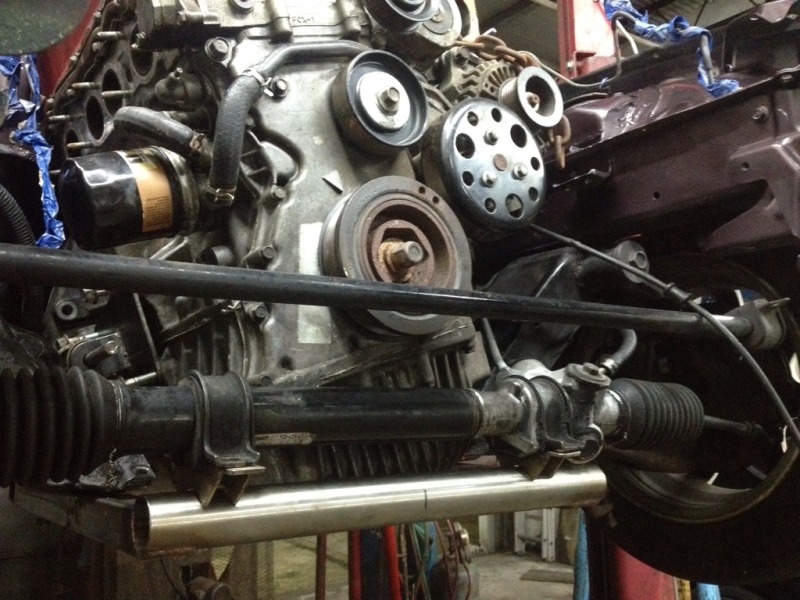
so here's where I sit at the end of day two
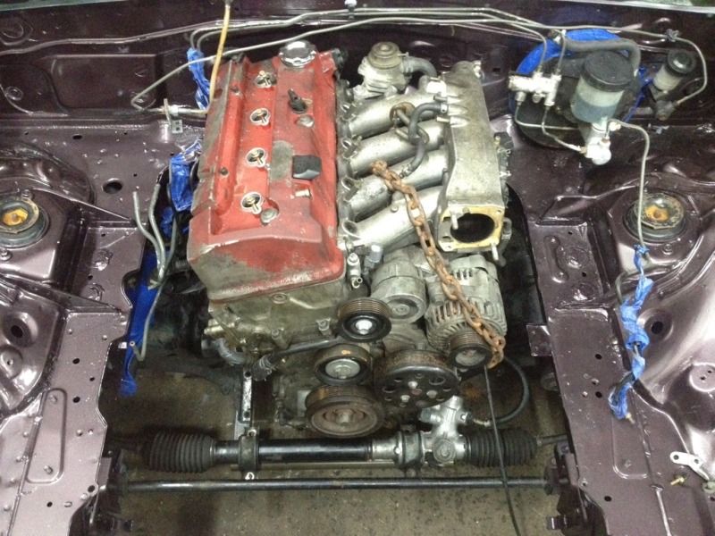
All I have left is the ppf adapter, a few hours of fab and welding to finish up the subframe, weld the mounts for rack, and lengthen the steering shaft. I'll post more tomorrow.
follow me on Instagram guys, I post all sorts of cool fab stuff there - zanderguerra
Here is the subframe addition, 1.25" square and 1.5" round, all tig welded.


I welded it onto the bottom of the subframe

And cut what I didn't want anymore away with a sawsall

I will be boxing In all of the open areas around the stock subframe, and adding a few reinforcements before this is done.

Engine shimmed and tweaked into position. Yes you loose ground clearance with this swap, the engine is too tall for the miata without being positioned farther back. I built it to sit a slight bit lower than the sump, to protect it.

Close up of the subframe side of the mounts

Don't mind the bolts not being in all the way, or there being a piece of stainless stock through the mount hole, it's all just mocked up in these photos.
Driver side

Passenger side

I have the steering rack mounts made and sitting in this picture, but it's not aligned or welded yet, I was tired and didn't feel like working anymore

so here's where I sit at the end of day two

All I have left is the ppf adapter, a few hours of fab and welding to finish up the subframe, weld the mounts for rack, and lengthen the steering shaft. I'll post more tomorrow.
#13
It's not only the distance, it's also that the rack is on the other side (rack in front of the knuckle) that make a change in behaviour.
#14
Copy in any discussion in the K24 thread.
It's not only the distance, it's also that the rack is on the other side (rack in front of the knuckle) that make a change in behaviour.
It's not only the distance, it's also that the rack is on the other side (rack in front of the knuckle) that make a change in behaviour.
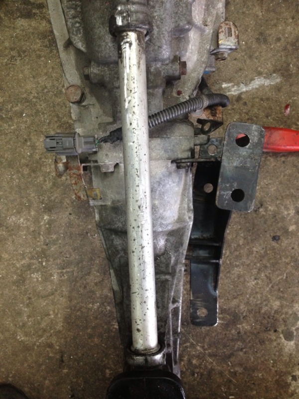
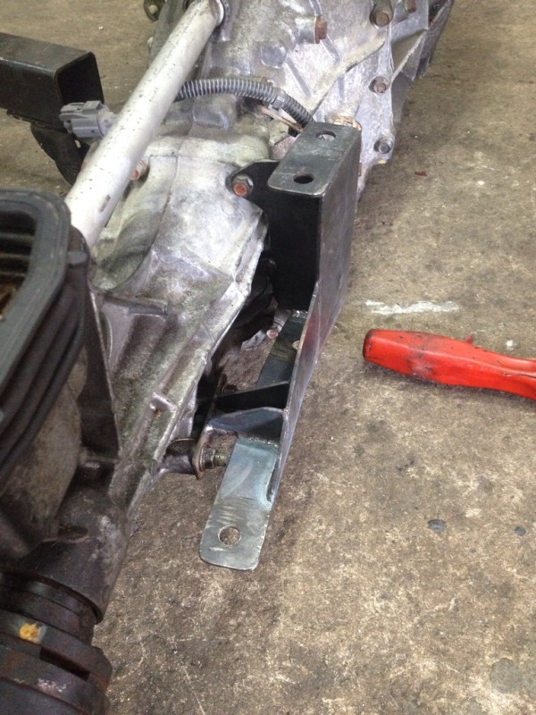
Anyways, here's the ppf adapter, probably overbuilt, but I like strength.
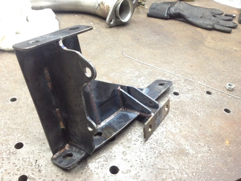
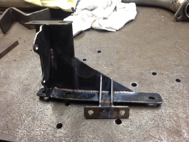
Almost done! Just superficial stuff now; boxing in the subframe and reinforcing it, and the steering shaft.
#16
And that's it, everything fits and mounts well, so I pulled the engine back out for the final time, so I could box in the subframe.
Here's the ppf adapter on the trans
That's it guys! Now I'm making fixtures of the mounts, and a fixture of the whole subframe with new steering rack mounts. That way I can make tubular subframes in the future.


Here's the ppf adapter on the trans


That's it guys! Now I'm making fixtures of the mounts, and a fixture of the whole subframe with new steering rack mounts. That way I can make tubular subframes in the future.


