When you click on links to various merchants on this site and make a purchase, this can result in this site earning a commission. Affiliate programs and affiliations include, but are not limited to, the eBay Partner Network.
As the title suggests, I want to share my take on making some DIY intakes. I have been working on this project to make some air intakes either for brakes or for cold air intake after getting some inspiration from a friend, and I thought maybe someone here would be interested in trying something similar and following the workflow. This is a slight piggybag from my previous thread on simulating some air ducts, where I convinced myself that a 3 inch pipe is better than a 2 inch: https://www.miataturbo.net/aerodynam...-thing-102161/
Straight to the thing:
1. In my case I have a fake GV-lip which has some premade positions to use as an air inlet, which made it a no-brainer for me to "choose" where I would take my air from.
2. After not making a choice where I will put my intakes, I made a image based 3D reconstruction of the lip, my splitter and the front suspension area of the car (the painters tape with marks is for providing a better surface for the reconstruction, shiny surface is a no-no):
3. After importing the scans to Catia, I proceeded to make a pretty basic and quick intake model (plus piping and an outlet at the brakeshield) with some quickly adjustable parameters like hose ID and wall thickness to make it easy to play around and make some prototypes with different dimensions. I 3D printed a couple of small test pieces to try on the car to make sure all dimensions are correct. The 3D scan seemed to be very accurate and I had to only do a few small adjustments.
4. For the real piece I chose to try to 3D print it with PETG for now, after doing some tests I decided to do it with 1.5mm wall thickness as it seems sufficient. I also did some tests on coating a section of a test print with some Araldite 2011 epoxy in order to see if I could improve the surface quality and the overall strength. Seems like answer is yes and yes to both questions, so I will end up doing some kind of coating on the final pieces aswell. Also it is nice to know that I can most likely coat the 3D printed pieces with something that will prevent the material from absorbing water and protect the printed piece from heat (looking at you mister brake shield).
Both finished pieces Detail 1 Detail 2 Coating test piece Seal against bumper and coating on test piece
Next steps are to decide what to use for the final coating of the pieces and install these to the car, after that make the counterpart in the brakeshield and install the pipe.
Looks good! I did something similar but used the NB2 foglight holes instead. Same with printing PETG and epoxy coating it for strength. I wish I had a 3d scanner, would love to make plugs for the GV lip to not allow airflow through it.
Added a lip so I could melt a wire mesh into the front side as well.
AxelWal, are you willing to share the 3D models?
I have been meaning to do exactly the same thing with the same lip and you would save me a ton of time.
Looks good! I did something similar but used the NB2 foglight holes instead. Same with printing PETG and epoxy coating it for strength. I wish I had a 3d scanner, would love to make plugs for the GV lip to not allow airflow through it.
Added a lip so I could melt a wire mesh into the front side as well.
That looks like a super nice execution, did you have any preference on which epoxy and how to apply it? I quite literally just winged it on the test piece and just swiped it on with the provided plastic spatula, but something more advanced would propably make my finished result a bit nicer.
Regarding the 3D scanning, I was a bit lazy so I literally did it with my phone and 3DF Zephyr for reconstruction one evening. You should check it out since it's free https://www.3dflow.net/3df-zephyr-pr...s-from-photos/
I would also have an access to a laser scanner but the required precision for this was not that high so bah.
Originally Posted by mfoote
AxelWal, are you willing to share the 3D models?
I have been meaning to do exactly the same thing with the same lip and you would save me a ton of time.
I do not quarantee that it will fit because my GV lip is fake like I mentioned But honestly why not, any preference on which format? STL to import it staight to Cura etc. or STP for Cad?
Also three things:
Can you give me a precise Inner Diameter of the hose you will use, because I will use a metric 69mm ID hose that I can get locally here I will leave some tolerance so that your hose should fit.
Any preference on wall thickness? I used only 1.5mm because PETG is pretty strong, but if you will print it in ABS or PLA you will need at least 2mm or 2.5mm to be safe I think.
With my hose diameter I am going to have to remove the plastic flap extension (gurney flap?) thing on bottom the bumper to make this design fit, since it does not fit between that and my splitter.
I would recommend printing a small segment first just to test the fitment on the lip before printing the whole thing, if there is only a small error I can quite easily adjust the model for you.
That looks like a super nice execution, did you have any preference on which epoxy and how to apply it? I quite literally just winged it on the test piece and just swiped it on with the provided plastic spatula, but something more advanced would propably make my finished result a bit nicer.
Regarding the 3D scanning, I was a bit lazy so I literally did it with my phone and 3DF Zephyr for reconstruction one evening. You should check it out since it's free https://www.3dflow.net/3df-zephyr-pr...s-from-photos/
I would also have an access to a laser scanner but the required precision for this was not that high so bah.
I used US Composites medium expoxy applied with a foam brush because it's what I had on hand. Can't say the finish is super nice but it does the job, especially for a hidden part like that.
Thanks, I'm going to have to check that out. That may help on future projects.
I used US Composites medium expoxy applied with a foam brush because it's what I had on hand. Can't say the finish is super nice but it does the job, especially for a hidden part like that.
Thanks, I'm going to have to check that out. That may help on future projects.
Your choice of epoxy looks a lot better than mine as it is actually recommended for filling porous surfaces, I have to see if I can find that lying around at work to try it out Thanks!
Probs someone who does not want their fake gv glassfiber lip to crack just by showing it an image of a speedbump Dunno I just assumed people don't buy fake **** like I do but maybe I am too naive
what do you reckon this would cost to print and epoxy per set ?
For my 1.5mm wall with 0.15mm layer height it was around 140grams of PETG per piece, one kilo of this black magic is around 30chf (~30usd) so around 5chf per piece. ABS or PLA is cheaper per kilo but you need to print a thicker wall for sure. I have the benefit of having access to a printer for free so I don't know how much ordering this would cost.
With epoxy your mileage propably varies, try find something similar to the US composites medium that was recommended before in the thread, my guess is like 5 or 10 usd for enough to coat one piece.
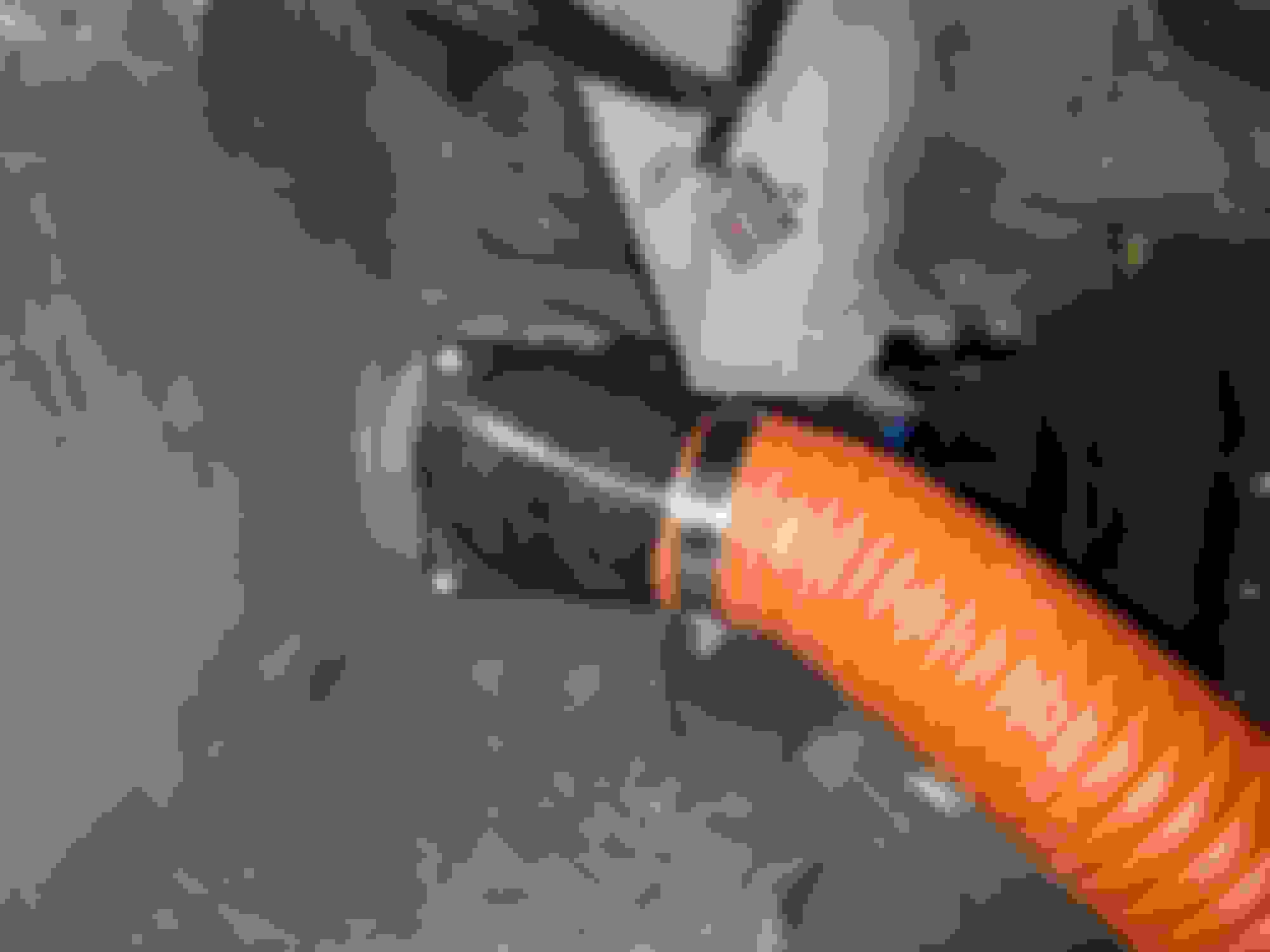
After considering some options I decided to go with epoxy for attachment to the lip. I don't expect to have to take them off very often after putting them on so I might aswell go for the clean looking solution, and if I ever neeed to get them of I can just break them and remove the extra material with a file or some ****. The tape is just for compression.

 03-04-2020, 07:51 AM


 2
2


 But honestly why not, any preference on which format? STL to import it staight to Cura etc. or STP for Cad?
 I will leave some tolerance so that your hose should fit.
 Thanks!