the thread where Savington asks a lot of really, really dumb questions.

 02-26-2010, 08:40 PM
#62
Former Vendor

Thread Starter
iTrader: (31)

Join Date: Nov 2006
Location: Sunnyvale, CA
Posts: 15,442
Total Cats: 2,103
OK, VVT is wired. One wire to +12v, one wire to INJ9 on the AEM.
On to the settings, and understanding WTF they do:
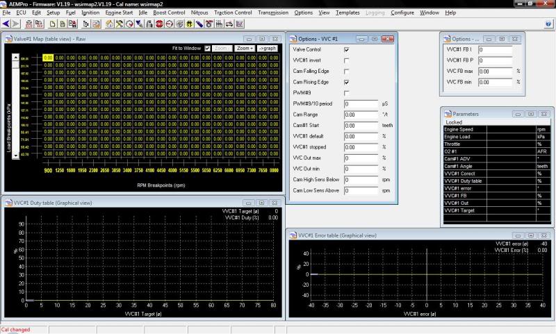
Starting lower left-hand corner, I assume this is the 2D table dictating what degree of advance/retard correlates to what percentage on the solenoid. The hard part about this is as Jason said - it's not a straight correlation, and we have to increase the duty to get the VVT to advance and then bring it back to stop advancing it. I think this map is basically going to get set so that the solenoid sees ~.54v, which is steady cam timing, across the board, and then use the error table to actually do the adjustment.
Upper left is the timing map. Load on Y, RPM on X. The cells are either duty cycle percentage or cam advance. Because you can't put negative numbers into these cells, I am thinking this is the duty cycle percentage, but then there's no negative numbers in the 2D table either, so maybe it's based on total degrees of advance from the max retard point (i.e. +12 would be 0deg adv/retard on the Miata, since there is a max of 12deg of retard).
Lower right is the money table, the timing error vs. duty cycle table. Because there is no direct correlation between the DC% and the advance, this is the table that will do the adjustment. As the RPMs increase and the desired retard increases, the error will get larger and larger, which will trigger duty in one direction or the other. As it gets closer to the target, the error decreases, brings the voltage back closer to .54, etc.
I have absolutely no idea what any of the stuff in the options box does. I think Cam Range would be the 360/number of teeth on the gear to get degrees per tooth, but I'm lost on the rest of it.
The VVT Feedback options, I figure the VVC FB min/max are the limits for the error table, but I don't know what the VVC#1 FB I/P settings do.
Tell me how wrong I am now, please
On to the settings, and understanding WTF they do:
Starting lower left-hand corner, I assume this is the 2D table dictating what degree of advance/retard correlates to what percentage on the solenoid. The hard part about this is as Jason said - it's not a straight correlation, and we have to increase the duty to get the VVT to advance and then bring it back to stop advancing it. I think this map is basically going to get set so that the solenoid sees ~.54v, which is steady cam timing, across the board, and then use the error table to actually do the adjustment.
Upper left is the timing map. Load on Y, RPM on X. The cells are either duty cycle percentage or cam advance. Because you can't put negative numbers into these cells, I am thinking this is the duty cycle percentage, but then there's no negative numbers in the 2D table either, so maybe it's based on total degrees of advance from the max retard point (i.e. +12 would be 0deg adv/retard on the Miata, since there is a max of 12deg of retard).
Lower right is the money table, the timing error vs. duty cycle table. Because there is no direct correlation between the DC% and the advance, this is the table that will do the adjustment. As the RPMs increase and the desired retard increases, the error will get larger and larger, which will trigger duty in one direction or the other. As it gets closer to the target, the error decreases, brings the voltage back closer to .54, etc.
I have absolutely no idea what any of the stuff in the options box does. I think Cam Range would be the 360/number of teeth on the gear to get degrees per tooth, but I'm lost on the rest of it.
The VVT Feedback options, I figure the VVC FB min/max are the limits for the error table, but I don't know what the VVC#1 FB I/P settings do.
Tell me how wrong I am now, please

Reply
 0
0

0
02-26-2010, 09:32 PM
#63
Elite Member

Join Date: Jul 2005
Posts: 6,420
Total Cats: 84
Keep VVT disconnected.
See if your setup can read cam phase to being with.
Rev it to ~3000 RPM. Apply 12V to solenoid.
See if it reads 47* less retard or more advance.
Double check too that in the cam/crank trigger advanced screen, that advancing the cam doesn't cause loss of sync.
Then let's discuss closing the loop.
Cam range I think is the # of crank teeth time that the cam can move around. With the factory 99 trigger wheel, you have 1 tooth per 180* of crank rotation. So 47* would be 0.261 teeth of range.
Later.
Reply
0
0
02-26-2010, 09:44 PM
#64
Elite Member
Join Date: Jul 2005
Posts: 6,420
Total Cats: 84
Starting lower left-hand corner, I assume this is the 2D table dictating what degree of advance/retard correlates to what percentage on the solenoid. The hard part about this is as Jason said - it's not a straight correlation, and we have to increase the duty to get the VVT to advance and then bring it back to stop advancing it. I think this map is basically going to get set so that the solenoid sees ~.54v, which is steady cam timing, across the board, and then use the error table to actually do the adjustment.
Later when you actually start tuning this, lets start with advance not changing with MAP but only changing with RPM. It will make tuning easier.
Upper left is the timing map. Load on Y, RPM on X. The cells are either duty cycle percentage or cam advance. Because you can't put negative numbers into these cells, I am thinking this is the duty cycle percentage
Lower right is the money table, the timing error vs. duty cycle table. Because there is no direct correlation between the DC% and the advance, this is the table that will do the adjustment.
Reply
0
0
02-26-2010, 09:59 PM
#65
Elite Member
Join Date: Jul 2005
Posts: 6,420
Total Cats: 84
VVC FB P and VVC FB I are the gain terms of the P and the I in the PI loop, respectively.
In AEM convention, you set these to be negative numbers, unless your system gain is inverted, such that more duty cycle decreases the thing you're measuring/targeting.
Because you're usually better off using the error table, set the P gain to 0.
The I gain should be very small, and it's only used to find the exact value of "hold the advance" duty cycle.
The FB max and min are the max allowed change in duty cycle as driven by the P and the I terms .... e.g. you put in +10% and -10%. As for the latter, I forget if the convention is positive or negative... if positive, the min will be -10.
Reply
0
0
02-27-2010, 01:57 AM
#66
Former Vendor
Thread Starter
iTrader: (31)
Join Date: Nov 2006
Location: Sunnyvale, CA
Posts: 15,442
Total Cats: 2,103
Correct. You will have to find the duty cycle such that it holds advance. I posted the estimated duty cycle in another thread. BTW this system will probably work better if you use ~100~200 Hz and you placed an SB530 diode backwards across the solenoid (cathode or stripe connects to the 12V side of the solenoid)

Wrong. This is your advance target vs RPM and load. It's just that "advance" is expressed as a non-zero number. So max retard would be 0 or close to 0, and max possible advance would be 47. WARNING - I may have it backwards, and the AEM may interpret this as RETARD - so that max advance may be near 0, and max retard will be 47. Do a search on the AEM electronics forum - you'll probably have most luck in the K20 section.
Reply
0
0
02-27-2010, 04:41 AM
#67
Elite Member
iTrader: (10)
Join Date: Jun 2006
Location: Athens, Greece
Posts: 5,987
Total Cats: 359
Jim
Reply
0
0
02-27-2010, 01:01 PM
#68
Elite Member
Join Date: Jul 2005
Posts: 6,420
Total Cats: 84
The standard output driver in the AEM has a voltage clamp, a 60V zener diode (built into the MOSFET). When the current to an inductor or solenoid is interrupted during the off time of the PWM signal, the inductor's voltage "flies" very high and is clamped to 60V. The current then decays rapidly. The SB340 clamps the voltage and prevents the current from decaying very rapidly. The net result is that the average current (over the duty cycle) follows the PWM duty cycle more closely and the solenoid will require less duty cycle to reach the target current. The main desired effect is that the current will be a more linear function of duty cycle, making it more predictable.
Reply
0
0
02-28-2010, 09:55 PM
#70
Former Vendor
Thread Starter
iTrader: (31)
Join Date: Nov 2006
Location: Sunnyvale, CA
Posts: 15,442
Total Cats: 2,103
Keep VVT disconnected.
See if your setup can read cam phase to being with.
Rev it to ~3000 RPM. Apply 12V to solenoid.
See if it reads 47* less retard or more advance.
Double check too that in the cam/crank trigger advanced screen, that advancing the cam doesn't cause loss of sync.
See if your setup can read cam phase to being with.
Rev it to ~3000 RPM. Apply 12V to solenoid.
See if it reads 47* less retard or more advance.
Double check too that in the cam/crank trigger advanced screen, that advancing the cam doesn't cause loss of sync.
The motor ran very rough, but it did maintain sync with +12v on the solenoid.
Cam range I think is the # of crank teeth time that the cam can move around. With the factory 99 trigger wheel, you have 1 tooth per 180* of crank rotation. So 47* would be 0.261 teeth of range.
Later.
Reply
0
0
03-03-2010, 11:39 AM
#72
Elite Member
Join Date: Jul 2005
Posts: 6,420
Total Cats: 84
Can you show your advance cam/crank sensor screen? There may be a setting there related to VVC.
If you get your settings to read, it should read some value under "Cam#1 ADV" and "Cam#1 Angle" even when running at full retard.
Do they read anything while idling?
If you get your settings to read, it should read some value under "Cam#1 ADV" and "Cam#1 Angle" even when running at full retard.
Do they read anything while idling?
Reply
0
0
03-05-2010, 12:53 PM
#73
Elite Member
Join Date: Jul 2005
Posts: 6,420
Total Cats: 84
Finally got round to installing the AEM s/w on my recently crashed laptop...
Cam range looks like simply a multiplier that scales teeth to displayed degrees.
I will assume it's crank teeth. So with the factory 2 tooth wheel, it's 180* per tooth.
Cam range looks like simply a multiplier that scales teeth to displayed degrees.
I will assume it's crank teeth. So with the factory 2 tooth wheel, it's 180* per tooth.
Reply
0
0
03-05-2010, 08:17 PM
#74
Former Vendor
Thread Starter
iTrader: (31)
Join Date: Nov 2006
Location: Sunnyvale, CA
Posts: 15,442
Total Cats: 2,103
The K20A calibration that comes with AEMPro uses 37.11 in that cell.
It may have been that I had the VVT control off - I'll turn it on in the software and try again today.
It may have been that I had the VVT control off - I'll turn it on in the software and try again today.
Reply
0
0
03-06-2010, 04:55 PM
#76
Former Vendor
Thread Starter
iTrader: (31)
Join Date: Nov 2006
Location: Sunnyvale, CA
Posts: 15,442
Total Cats: 2,103
Where is the god damn fan control page? I am getting tired of the fans kicking on and off a bajillion times a second because there's no hysteresis because I can't find the page to add some.
Reply
0
0
03-06-2010, 05:09 PM
#77
Former Vendor
Thread Starter
iTrader: (31)
Join Date: Nov 2006
Location: Sunnyvale, CA
Posts: 15,442
Total Cats: 2,103
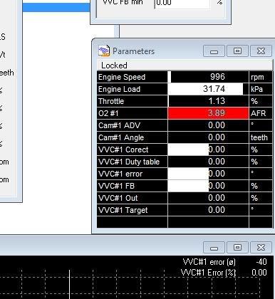
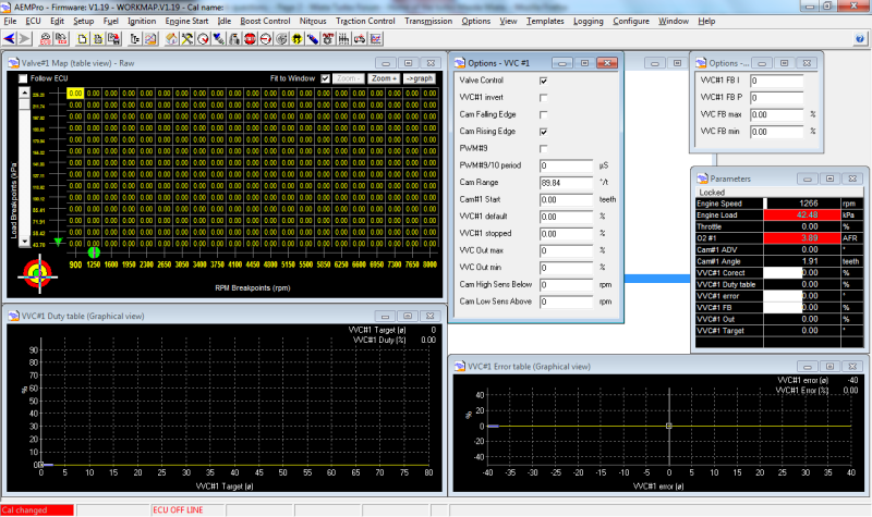
3000rpm, Valve control on, */teeth set to ~90, no change. The car usually idles around 29-30kpa, at 300rpm as soon as I hit the solenoid with 12v, the RPMs drop to 1800, 60kpa, runs rough, and the cam angle drops from ~1.9 to ~1.6.
Reply
0
0
03-06-2010, 06:16 PM
#78
Elite Member
iTrader: (22)

Join Date: Dec 2006
Location: Sunny Spanish speaking Non US Caribbean
Posts: 3,224
Total Cats: 3
If you're using AEM PRO. Go to: "Options", hit "List Selection" and then unlock: "Radiator Fan". Set temp Off and On. Done.
Reply
0
0


