ismael_pt Adaptronic installation (DIY harness)
 05-25-2009, 10:27 AM
#61
Junior Member
Thread Starter
iTrader: (1)

Join Date: Aug 2008
Location: Granada, Spain
Posts: 341
Total Cats: 2
Rafa, it's a parallel installation. The alternator controlled by the stock ecu.
The AC does not work either, and all of these functions are wired directly to the stock ecu. I have a hypothesis of what is going on: CKP and CAS wires are disconnected from the stock ecu, only the adaptronic is reading the CKP and CAS signals, the tachometer in the dash don't work, probably because it's not receiving signal from CKP or CAS. Maybe the problem is that the stock ecu don't interact with the alternator until it sees a minimal amount of rpm.
Could someone with more knowledge than me confirm that?
The AC does not work either, and all of these functions are wired directly to the stock ecu. I have a hypothesis of what is going on: CKP and CAS wires are disconnected from the stock ecu, only the adaptronic is reading the CKP and CAS signals, the tachometer in the dash don't work, probably because it's not receiving signal from CKP or CAS. Maybe the problem is that the stock ecu don't interact with the alternator until it sees a minimal amount of rpm.
Could someone with more knowledge than me
confirm that?

Reply
 0
0

0

 05-28-2009, 08:59 AM
#64
Junior Member
Thread Starter
iTrader: (1)
Join Date: Aug 2008
Location: Granada, Spain
Posts: 341
Total Cats: 2
I have just repaired my exhaust manifold and expect it won't crack again.
Still can't share CKP and CAS signal between the two ecus I tried with and without diodes, re-do the connections, re-check the connections, I play with triggers setup... but nothing works.
Any ideas?
Still can't share CKP and CAS signal between the two ecus
I tried with and without diodes, re-do the connections, re-check the connections, I play with triggers setup... but nothing works.Any ideas?
Reply
0
0
 05-28-2009, 03:42 PM
#67
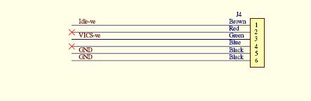
1 I have the drawing of my loom.
2 I'm an electronics guy, so reading the drawing is easy for me.
For power ==> voltage x current = power.
Think in a sinus shipe. Using a zenerdiode has the result that the diode let trough the sinusshape but with a slightly longer zero time. result is that the shape of the signal is modified. the signal is smaller. a smaller signal is a smaller voltage. Look to the formula above ==> with a smaller voltage there is less power usage.
Reply
0
0
05-28-2009, 03:52 PM
#68
Junior Member
Thread Starter
iTrader: (1)
Join Date: Aug 2008
Location: Granada, Spain
Posts: 341
Total Cats: 2
I purchased and installed BAT85 (the same that y8s is using) and now the two ecus have signal.
The car runs, with the throttle open, I need to set the idle parameters. With the default map the min DC for the idle valve is 60, but if I lift the throttle the car dies.
The car runs, with the throttle open, I need to set the idle parameters. With the default map the min DC for the idle valve is 60, but if I lift the throttle the car dies.
Reply
0
0
05-28-2009, 05:21 PM
#71
2 Props,3 Dildos,& 1 Cat


iTrader: (8)
Join Date: Jun 2005
Location: Fake Virginia
Posts: 19,338
Total Cats: 573
check idle Air/fuel ratio too. start in the high 13s for stability. your idle settings should have max authority set from 10-15 to about 85-90.
Reply
0
0
05-28-2009, 05:42 PM
#72
Junior Member
Thread Starter
iTrader: (1)
Join Date: Aug 2008
Location: Granada, Spain
Posts: 341
Total Cats: 2
The Adaptronic is connected to the idle valve in this way:
2Q to J4-1 (Aux. out 1 in the adaptronic)
2P directly to the stock ecu
Should they be wired that way, right?
Reply
0
0
05-28-2009, 05:52 PM
#73
2 Props,3 Dildos,& 1 Cat
iTrader: (8)
Join Date: Jun 2005
Location: Fake Virginia
Posts: 19,338
Total Cats: 573
I tried all kind of configurations and the idle valve doesn't seem to change. It does the same at whatever value is changed.
The Adaptronic is connected to the idle valve in this way:
2Q to J4-1 (Aux. out 1 in the adaptronic)
2P directly to the stock ecu
Should they be wired that way, right?
The Adaptronic is connected to the idle valve in this way:
2Q to J4-1 (Aux. out 1 in the adaptronic)
2P directly to the stock ecu
Should they be wired that way, right?
Reply
0
0
 05-29-2009, 11:38 AM
#77
Junior Member
Thread Starter
iTrader: (1)
Join Date: Aug 2008
Location: Granada, Spain
Posts: 341
Total Cats: 2
update (and request of help):
Today the idle valve has started to work, but only in 100hz or lower values and making the annoying noise. Any higher value don't hold the idle speed and the car dies.
Also the CLT signal is noisy, something similar to this https://www.miataturbo.net/forum/t33414/
Somebody knows where is the ground wire of the CLT located in the 01+?
The IAT sensor (GM) is reading 3300+- ADC for a ambient temperature of 25� C, I think this is not normal. Maybe is related to the CLT noise problem.
The car start after a few attempts and only if I press the throttle while cranking. Could you guys take a look at my cranking fuel numbers?
Reply
0
0
05-29-2009, 04:01 PM
#78
Junior Member
Thread Starter
iTrader: (1)
Join Date: Aug 2008
Location: Granada, Spain
Posts: 341
Total Cats: 2
idle problem solved: min. 68 max. 100 DC @ 500hz, don't make noise and reach the target idle speed of 1000 rpm.
I also located and disconnected the chassis ground wire for the CLT, but it's still fluctuating.
Remaining problems: IAT calibration, CLT signal and cranking fuel (stock 1.8 01+ injectors)
I also located and disconnected the chassis ground wire for the CLT, but it's still fluctuating.
Remaining problems: IAT calibration, CLT signal and cranking fuel (stock 1.8 01+ injectors)
Reply
0
0
05-29-2009, 06:45 PM
#79
Elite Member
iTrader: (22)

Join Date: Dec 2006
Location: Sunny Spanish speaking Non US Caribbean
Posts: 3,224
Total Cats: 3
idle problem solved: min. 68 max. 100 DC @ 500hz, don't make noise and reach the target idle speed of 1000 rpm.
I also located and disconnected the chassis ground wire for the CLT, but it's still fluctuating.
Remaining problems: IAT calibration, CLT signal and cranking fuel (stock 1.8 01+ injectors)
I also located and disconnected the chassis ground wire for the CLT, but it's still fluctuating.
Remaining problems: IAT calibration, CLT signal and cranking fuel (stock 1.8 01+ injectors)
I still don't understand why you didn't take this opportunity to put in the 440cc injectors. Habr�a sido un solo co�azo.
Reply
0
0

Thread
Thread Starter
Forum
Replies
Last Post
Zaphod
MEGAsquirt
47
10-26-2018 11:00 PM
stoves
Suspension, Brakes, Drivetrain
5
04-21-2016 03:00 PM


